
Electric Brake Wiring Diagram Trailer
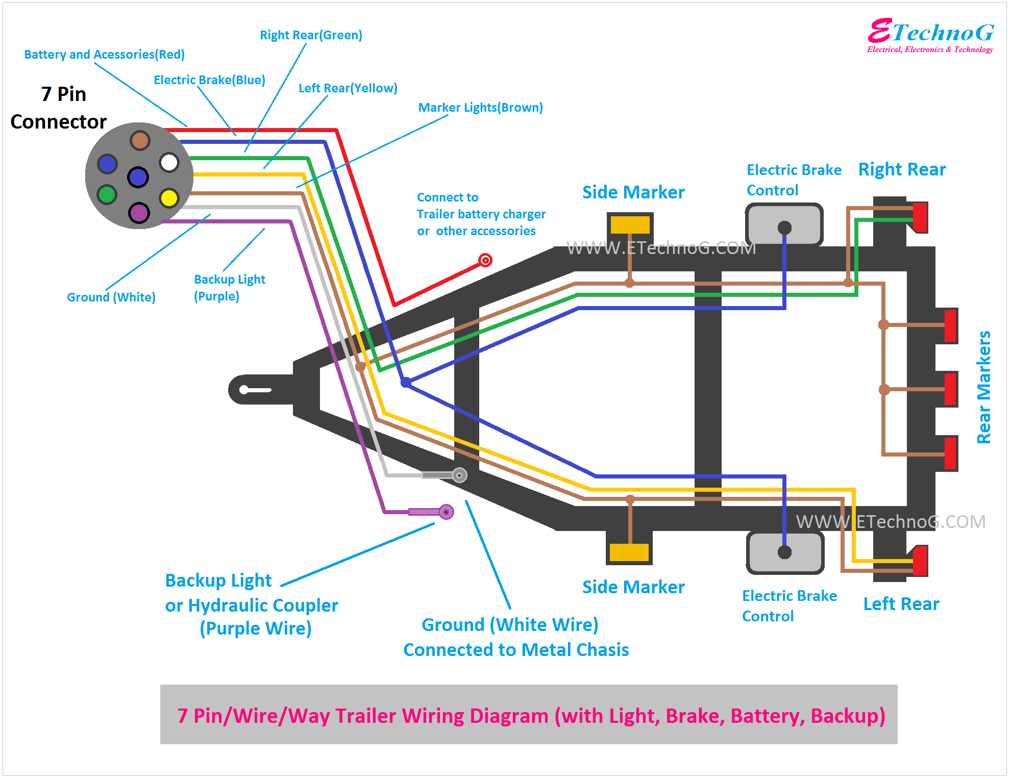
Understanding your trailer's electric brake wiring diagram is crucial for anyone who tows regularly, performs their own vehicle maintenance, or enjoys modifying their equipment. Whether you're diagnosing a brake malfunction, installing a new brake controller, or simply wanting to understand how your trailer's braking system integrates with your tow vehicle, this guide will provide you with the necessary knowledge. We'll cover the purpose of the diagram, key components, common symbols, how the system works, troubleshooting tips, and essential safety precautions. We also have a downloadable copy of a standard electric brake wiring diagram available for you. Knowing how to read and use this diagram empowers you to handle repairs and upgrades confidently, saving you time and money in the long run.
Purpose of the Wiring Diagram
An electric brake wiring diagram serves as a visual roadmap of the electrical connections within your trailer's braking system. It's more than just a pretty picture; it's an essential tool for:
- Diagnostics: Pinpointing the source of a brake problem, such as a short circuit, open circuit, or faulty component.
- Repairs: Guiding you through the correct reconnection of wires after a repair or replacement.
- Installation: Assisting with the proper wiring of new brake components, such as brake controllers or magnets.
- Understanding: Gaining a deeper understanding of how the electric brake system functions, which can aid in preventive maintenance.
- Modification: Safely adding new features or modifying existing circuits, such as adding breakaway switches or auxiliary lighting.
Key Specs and Main Parts
Before diving into the diagram, it's important to familiarize yourself with the key components of an electric brake system and their associated specifications. This understanding will make the diagram much easier to interpret.
Main Parts:
- Brake Controller: Located in the tow vehicle, the brake controller sends an electrical signal to the trailer's brakes when the driver applies the brakes. Modern controllers are often proportional, meaning the voltage sent to the trailer brakes is proportional to the tow vehicle's braking force.
- Seven-Way Connector: This connector, often referred to as a 7-pin connector, provides the electrical connection between the tow vehicle and the trailer. It carries signals for running lights, turn signals, brake lights, auxiliary power, and, most importantly, the electric brake signal.
- Electric Brake Assemblies: Located inside each wheel hub on the trailer, these assemblies contain an electromagnet that, when energized, attracts an armature, which in turn applies the brakes.
- Electromagnets: The heart of the electric brake system. These electromagnets are responsible for actuating the braking force. Their resistance is a critical specification, typically falling within a specific range (e.g., 3-4 ohms per magnet).
- Breakaway Switch: A crucial safety device. If the trailer becomes detached from the tow vehicle, the breakaway switch activates the trailer brakes, preventing a runaway trailer.
- Wiring: The wiring harness connecting all the components must be of sufficient gauge (thickness) to handle the electrical current. Wire gauge is typically specified in American Wire Gauge (AWG). Lower AWG numbers indicate thicker wires, capable of carrying more current.
Key Specs:
- Voltage: Electric brake systems typically operate on 12 volts DC.
- Current (Amperage): The current draw depends on the number of brakes and the resistance of the electromagnets. A typical two-axle trailer with four brakes can draw around 10-12 amps when the brakes are fully applied.
- Wire Gauge (AWG): The appropriate wire gauge depends on the current draw and the length of the wire run. A heavier gauge wire is needed for longer runs to minimize voltage drop. A common gauge for the main brake wire is 12 AWG or 10 AWG.
- Magnet Resistance: The resistance of each electromagnet is a crucial indicator of its health. A resistance outside the specified range (typically 3-4 ohms) indicates a faulty magnet.
Symbols in the Wiring Diagram
Understanding the symbols used in the wiring diagram is essential for accurate interpretation. Here are some common symbols you'll encounter:
- Solid Lines: Represent electrical wires. The thickness of the line might indicate the wire gauge.
- Dashed Lines: Might indicate a shielded cable or a physical connection (e.g., a wire running inside a protective conduit).
- Circles: Often represent connection points, such as terminals or splices.
- Squares/Rectangles: Can represent various components, such as the brake controller, breakaway switch, or junction boxes. The label inside the rectangle will indicate the component.
- Resistor Symbol (Zig-zag line): Represents the electromagnet within the brake assembly.
- Ground Symbol (Stacked horizontal lines): Indicates a connection to the chassis ground.
- Color Codes: Wires are often color-coded to aid in identification. Common colors include:
- Blue: Typically used for the electric brake wire.
- White: Typically used for the ground wire.
- Brown: Typically used for tail and running lights.
- Yellow: Typically used for left turn and brake light.
- Green: Typically used for right turn and brake light.
- Red: Often used for auxiliary power.
- Black: Often used for the battery feed.
A legend is usually provided with the diagram, explaining the symbols and color codes used.
How It Works
The electric brake system works in conjunction with the tow vehicle's braking system. Here's a simplified explanation:
- When the driver applies the brakes in the tow vehicle, the brake controller senses this action.
- The brake controller sends a variable voltage signal (proportional to the braking force) through the blue wire in the seven-way connector to the trailer.
- This voltage energizes the electromagnets in the trailer's brake assemblies.
- The energized electromagnets attract the armature inside the brake drum.
- The movement of the armature applies the brake shoes against the inside of the brake drum, slowing the trailer.
- The breakaway switch provides a fail-safe mechanism. If the trailer disconnects from the tow vehicle, the breakaway switch pulls a pin, completing a circuit that directly energizes the trailer brakes, bringing the trailer to a stop.
Real-World Use - Basic Troubleshooting Tips
Here are some common electric brake problems and how the wiring diagram can help you troubleshoot them:
- No Brakes: Use a multimeter to check for voltage at the brake magnets when the brake controller is activated. If there's no voltage, check the brake controller, the wiring between the controller and the seven-way connector, and the wiring within the trailer. If there's voltage, the magnets may be faulty.
- Weak Brakes: Could be caused by low voltage to the magnets, worn brake shoes, or improperly adjusted brakes. Check the voltage at the magnets under load. Inspect the brake shoes and adjust the brakes according to the manufacturer's specifications.
- Brakes Lock Up: Can be caused by a faulty brake controller, short circuit in the wiring, or a sticking brake assembly. Check the brake controller settings. Inspect the wiring for shorts or damage. Disassemble and clean the brake assemblies.
- One Brake Not Working: Use the wiring diagram to trace the wiring from the seven-way connector to the individual brake assembly. Check for loose connections, corroded terminals, or broken wires. Test the magnet's resistance.
Remember, always disconnect the trailer from the tow vehicle's electrical system before performing any troubleshooting or repairs.
Safety Precautions
Working with electrical systems can be dangerous. Here are some essential safety precautions:
- Disconnect Power: Always disconnect the trailer from the tow vehicle and any external power sources before working on the electrical system.
- Battery: Disconnect the trailer battery, if equipped.
- Use Proper Tools: Use properly insulated tools designed for electrical work.
- Wear Safety Glasses: Protect your eyes from sparks and debris.
- Inspect Wiring: Carefully inspect wiring for damage, such as frayed insulation or corroded terminals. Replace damaged wiring immediately.
- Brake Controller: Be careful around the brake controller as shorts here can damage it or the towing vehicle's electrical system.
Warning: The breakaway switch circuit can deliver full battery voltage directly to the trailer brakes. Exercise extreme caution when working on this circuit.
If you are not comfortable working with electrical systems, consult a qualified technician.
We have a standard electric brake wiring diagram available for download. It provides a visual guide that complements the information discussed in this article. This diagram can be a valuable resource when diagnosing and repairing your trailer's electric brake system. Please click here to download the diagram.