
Electric Fan Wiring Diagram With Relay
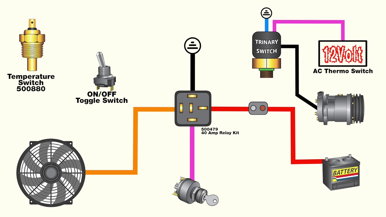
Let's dive into electric fan wiring diagrams that incorporate a relay. This configuration is incredibly useful for controlling electric cooling fans in automotive applications, offering enhanced performance and reliability compared to simpler, direct wiring setups. Whether you're retrofitting an older vehicle, upgrading your cooling system, or troubleshooting existing problems, understanding this wiring scheme is invaluable. We'll break down the key components, how they interact, and provide you with the knowledge to confidently work with this system.
Purpose and Benefits of Using a Relay
Why go through the extra effort of using a relay? The primary reason is to protect your vehicle's electrical system. Electric cooling fans, especially high-performance models, can draw a significant amount of current – often 20 amps or more. Without a relay, this entire current load would pass through the ignition switch or temperature sensor, potentially overloading and damaging these components. A relay acts as a switch, allowing a small control signal (from the ignition switch or temperature sensor) to activate a separate, high-current circuit dedicated solely to powering the fan. This provides several benefits:
- Reduced Load on Control Circuits: Protects sensitive components like the ignition switch and temperature sensors.
- Improved Fan Performance: Ensures the fan receives full voltage, maximizing its cooling capacity.
- Increased Reliability: Minimizes the risk of electrical failures and extends the lifespan of electrical components.
- Flexibility: Enables more complex control strategies, such as variable fan speed control based on engine temperature.
Key Specs and Main Parts of the Wiring Diagram
Before we examine the diagram itself, let's identify the key components and their specifications. Keep in mind that specific values may vary depending on your application, so always consult the manufacturer's documentation for your chosen components.
- Electric Cooling Fan: The heart of the system. Choose a fan with sufficient CFM (cubic feet per minute) rating for your engine's cooling needs. Consider the amp draw of the fan – this is crucial for selecting the correct relay and wiring.
- Relay: A 4- or 5-pin automotive relay is typically used. The relay's contacts are rated for a specific amperage. Select a relay with a rating significantly higher than the fan's amp draw (e.g., a 30-amp relay for a 20-amp fan).
- Temperature Sensor or Switch: This component monitors engine temperature and triggers the fan when a predetermined threshold is reached. Common types include threaded temperature sensors that screw into the engine block or radiator. Select a sensor with the appropriate temperature activation point for your engine.
- Fuse: A critical safety device that protects the circuit from overcurrent. The fuse should be sized slightly above the fan's continuous amp draw. A 25- or 30-amp fuse is common.
- Wiring: Use automotive-grade wiring of the appropriate gauge (thickness) for the current load. 12- or 10-gauge wire is commonly used for the fan's power and ground circuits. Refer to a wiring gauge chart to ensure you're using the correct size.
- Ground Connection: A secure connection to the vehicle's chassis. This is essential for completing the circuit and ensuring proper fan operation.
- 12V Power Source: Typically, the battery or a fused ignition-switched power source. Using a direct battery connection allows the fan to run even when the ignition is off, which can be beneficial in hot climates.
Understanding the Wiring Diagram Symbols
Wiring diagrams use standardized symbols to represent electrical components and connections. Here’s a breakdown of common symbols you'll encounter in an electric fan wiring diagram:
- Solid Lines: Represent wires. The thickness of the line may indicate the wire gauge (thicker lines generally represent thicker wires).
- Dashed Lines: Often indicate a ground connection or a wire hidden behind other components.
- Circles with a "T" inside: Represent a ground connection.
- Rectangle with a zigzag line: Represents a resistor (often used in more complex fan speed control circuits).
- Relay Symbol: Typically shows a coil (represented by a looped wire) and a set of contacts (represented by two lines that can be either connected or disconnected).
- Fuse Symbol: A small rectangle with a wavy or zigzag line inside.
- Battery Symbol: A series of short and long parallel lines.
- Color Coding: Wires are often color-coded to aid in identification. Common colors include red (power), black (ground), and other colors for control signals. Always refer to the specific diagram's legend for color code definitions.
How the Wiring Works
Let's trace the flow of electricity through the circuit:
- Power Supply: A 12V power source (battery or ignition-switched) is connected to the relay's power input (typically terminal 30 on a standard automotive relay). A fuse is placed inline to protect the circuit.
- Ground Connection: The fan itself has a dedicated ground wire that is securely connected to the vehicle's chassis.
- Control Signal: The temperature sensor or switch is connected to the relay's control circuit (typically terminal 86). When the engine reaches the predetermined temperature, the sensor closes the circuit, providing a path to ground for the relay coil.
- Relay Activation: When the relay coil is energized (terminal 86 receives ground), it creates an electromagnetic field that pulls the relay's contacts together.
- Fan Power: When the relay contacts close, power flows from the relay's power input (terminal 30) through the closed contacts to the fan's power wire (typically terminal 87).
- Fan Operation: The fan now receives power and begins to spin, drawing air through the radiator and cooling the engine.
- Deactivation: When the engine temperature drops below the sensor's activation point, the sensor opens the circuit, de-energizing the relay coil. The relay contacts open, cutting power to the fan, and the fan stops spinning.
Real-World Use: Basic Troubleshooting Tips
Here are some common issues and troubleshooting steps:
- Fan Not Working:
- Check the fuse. A blown fuse is the most common cause. Replace with a fuse of the correct amperage.
- Verify the ground connection. A poor ground connection can prevent the fan from operating. Clean and tighten the ground connection.
- Test the relay. You can use a multimeter to check the relay's continuity and operation. You can also swap it with a known good relay to see if that resolves the issue.
- Check the temperature sensor. Use a multimeter to check its resistance at different temperatures. Consult the manufacturer's specifications to determine if it's functioning correctly.
- Inspect the wiring for damage or corrosion. Replace any damaged wiring.
- Fan Runs Constantly:
- Check the temperature sensor. It may be faulty and stuck in the "on" position.
- The relay may be stuck closed. Try replacing the relay.
- The wiring to the temperature sensor may be shorted to ground. Inspect the wiring for damage.
Safety Precautions
Working with automotive electrical systems involves inherent risks. Always disconnect the negative battery cable before working on any electrical components. Be particularly careful when working with the 12V power source and the relay. Incorrect wiring can lead to short circuits, fires, and damage to electrical components. Ensure you are using appropriate tools for crimping and stripping wires, and always double-check your connections before reconnecting the battery.
The relay, although small, handles high current. A malfunctioning relay can overheat and pose a fire hazard. Always use a relay rated for the appropriate amperage for your electric fan.
Remember, this guide provides a general overview. Always consult the specific wiring diagram for your vehicle or electric fan setup. Precise wiring and component placement can vary significantly depending on the application.
We have a downloadable PDF version of a typical electric fan wiring diagram with a relay available. Contact us to get the file, and happy wrenching!