Electric Radiator Fan Wiring Diagram
Alright, let's dive into the world of electric radiator fan wiring diagrams. Understanding this seemingly complex maze of wires is crucial for any serious DIY mechanic, car modder, or even just a savvy car owner. Whether you're troubleshooting a malfunctioning cooling system, upgrading to an aftermarket fan, or simply want to understand how your car *really* works, knowing how to read and interpret these diagrams is invaluable. We're going to break it down in a way that's clear, concise, and most importantly, practical.
Why Bother With the Wiring Diagram?
Why should you bother wrestling with a wiring diagram? Simple: because it gives you the power to diagnose problems, repair faults, and even upgrade your cooling system with confidence. Imagine your car overheating on a hot day. Do you blindly replace parts, hoping for the best? Or do you consult the wiring diagram, trace the circuit, and pinpoint the *exact* cause, saving time, money, and a whole lot of frustration? The diagram is your roadmap to understanding the electric fan's circuitry.
Specifically, you might need a diagram to:
- Troubleshoot a non-functional fan: Determine if the issue is a blown fuse, a faulty relay, a bad temperature sensor, a wiring break, or a dead fan motor.
- Install an aftermarket fan: Safely and correctly wire a new electric fan, ensuring proper operation and preventing damage to your electrical system.
- Upgrade your cooling system: Incorporate features like manual fan control or staged fan operation (two fans running at different speeds based on temperature).
- Understand your vehicle's electrical system: Gain a deeper understanding of how various components interact within your car's electrical system.
Key Specs and Main Parts
Before we dissect the diagram, let's identify the key components involved in a typical electric radiator fan circuit. These are the actors in our electrical drama:
- Electric Fan Motor: This is the heart of the system, converting electrical energy into rotational energy to move air across the radiator. DC motors are commonly used, requiring proper polarity (positive and negative connections).
- Temperature Sensor (Coolant Temperature Sensor - CTS): This sensor monitors the coolant temperature and sends a signal to the ECU (Engine Control Unit) or directly to a relay to activate the fan. Sometimes it's a simple on/off switch at a set temp; others are variable resistance sensors feeding data to the ECU.
- Relay: A relay acts as an electrically controlled switch. It uses a small current from the temperature sensor (or ECU) to control a larger current to the fan motor. Relays are crucial because the temperature sensor often can't handle the high current required by the fan. We need to switch a small current (sensor signal) to engage a large current (power to the fan).
- Fuse: A safety device that protects the circuit from overcurrent. If too much current flows through the circuit (due to a short circuit, for example), the fuse will blow, interrupting the flow of electricity and preventing damage to other components.
- ECU (Engine Control Unit): In many modern vehicles, the ECU controls the fan based on various parameters like coolant temperature, vehicle speed, and air conditioning demand.
- Wiring: Conductors that connect all the components, carrying electrical current. Wire gauge (thickness) is important; thicker wires can handle more current.
- Battery: Provides the necessary voltage (typically 12V DC) to power the entire system.
- Ground: The return path for the electrical current, completing the circuit. A good, solid ground connection is essential for proper operation.
Typical fan motor specs include voltage (12V DC is almost always), amperage draw (which can vary widely depending on the fan size and design – check the manufacturer's specs), and physical dimensions. The temperature sensor will have a specified temperature range at which it activates the fan.
Symbols: Deciphering the Code
Wiring diagrams use a standardized set of symbols to represent electrical components and connections. Learning these symbols is like learning a new language – it unlocks the diagram's secrets.
- Lines: Solid lines represent wires. Dashed lines often indicate shielding or signal lines. The thickness of the line *usually* but not always implies the wire gauge (thicker line = thicker wire).
- Circles: Often represent connections or terminals.
- Rectangles: Typically represent components like relays, fuses, or the ECU.
- Squiggly Line: Represents a resistor (or in this context, inside a sensor).
- Diode Symbol (Triangle pointing to a line): Allows current to flow in only one direction. Sometimes used in fan circuits to protect the ECU from voltage spikes.
- Ground Symbol (Usually a series of descending lines): Indicates the point where the circuit is connected to the vehicle's chassis for grounding.
- Colors: Wires are often color-coded to aid in identification. Common colors include red (power), black (ground), blue, green, yellow, and white. Refer to the diagram's legend for specific color coding information.
Important Note: Wiring diagrams can vary slightly depending on the vehicle manufacturer and model year. Always consult the specific wiring diagram for your vehicle for accurate information. A generic wiring diagram can serve as a starting point, but the vehicle-specific version is *essential*.
How It Works
The basic principle behind an electric radiator fan circuit is relatively straightforward. When the coolant temperature reaches a certain threshold, the temperature sensor triggers the fan to turn on. Here's a simplified explanation:
- The ignition switch is turned on, providing power to the system.
- The coolant temperature rises as the engine warms up.
- When the coolant temperature reaches the activation point of the temperature sensor, the sensor closes its contacts (completes the circuit).
- This sends a small current to the relay coil, energizing the relay.
- The energized relay closes its contacts, allowing a larger current to flow from the battery, through the fuse, to the electric fan motor.
- The fan motor spins, drawing air across the radiator to cool the coolant.
- When the coolant temperature drops below the sensor's deactivation point, the sensor opens its contacts, de-energizing the relay.
- The relay opens its contacts, cutting off power to the fan motor, and the fan stops spinning.
In systems controlled by the ECU, the temperature sensor sends a signal to the ECU, which then determines whether to activate the fan based on a more complex set of parameters. The ECU then signals the relay to turn the fan on or off.
Real-World Use: Basic Troubleshooting
Okay, so the fan's not working. What do you do? Here's a basic troubleshooting approach, guided by the wiring diagram:
- Check the Fuse: This is the easiest and most common fix. Use a multimeter to test the fuse for continuity. If it's blown, replace it with a fuse of the *same* amperage rating.
- Test the Relay: You can test the relay by applying power to the coil terminals and checking for continuity between the switch terminals. If the relay doesn't click when energized or if there's no continuity when it's supposed to be closed, replace it.
- Check the Fan Motor: Apply direct power (12V DC) to the fan motor leads. If the fan doesn't spin, the motor is likely faulty and needs to be replaced.
- Test the Temperature Sensor: Use a multimeter to check the sensor's resistance at different temperatures. Compare your readings to the sensor's specifications. If the resistance is out of range, replace the sensor.
- Check the Wiring: Look for damaged, corroded, or loose wires and connectors. Use a multimeter to check for continuity in the wiring. Repair or replace any faulty wiring.
- ECU Issues: If everything else checks out, the problem *could* be with the ECU. This is more complex and may require professional diagnosis.
Safety First!
Working with electrical systems can be dangerous. Always take the following precautions:
- Disconnect the Battery: Before working on any electrical components, disconnect the negative (-) terminal of the battery to prevent accidental shorts or shocks.
- Use Proper Tools: Use insulated tools designed for electrical work.
- Avoid Water: Never work on electrical systems in wet conditions.
- Be Aware of High-Voltage Components: Some components, like the ignition system, can carry high voltages even after the engine is turned off. Exercise extreme caution when working near these components.
- Fuses: Never replace a fuse with one of a higher amperage rating. This can overload the circuit and cause a fire.
- Relays can switch high currents; always ensure proper voltage and current ratings when replacing them.
The Condenser on your AC system may have residual charge and could provide a shock if touched. Deplete the stored charge if servicing.
We've covered a lot, from the purpose of wiring diagrams to troubleshooting tips. Remember, patience and a systematic approach are your best allies when tackling electrical repairs. Always consult the specific wiring diagram for your vehicle, and when in doubt, seek professional help.
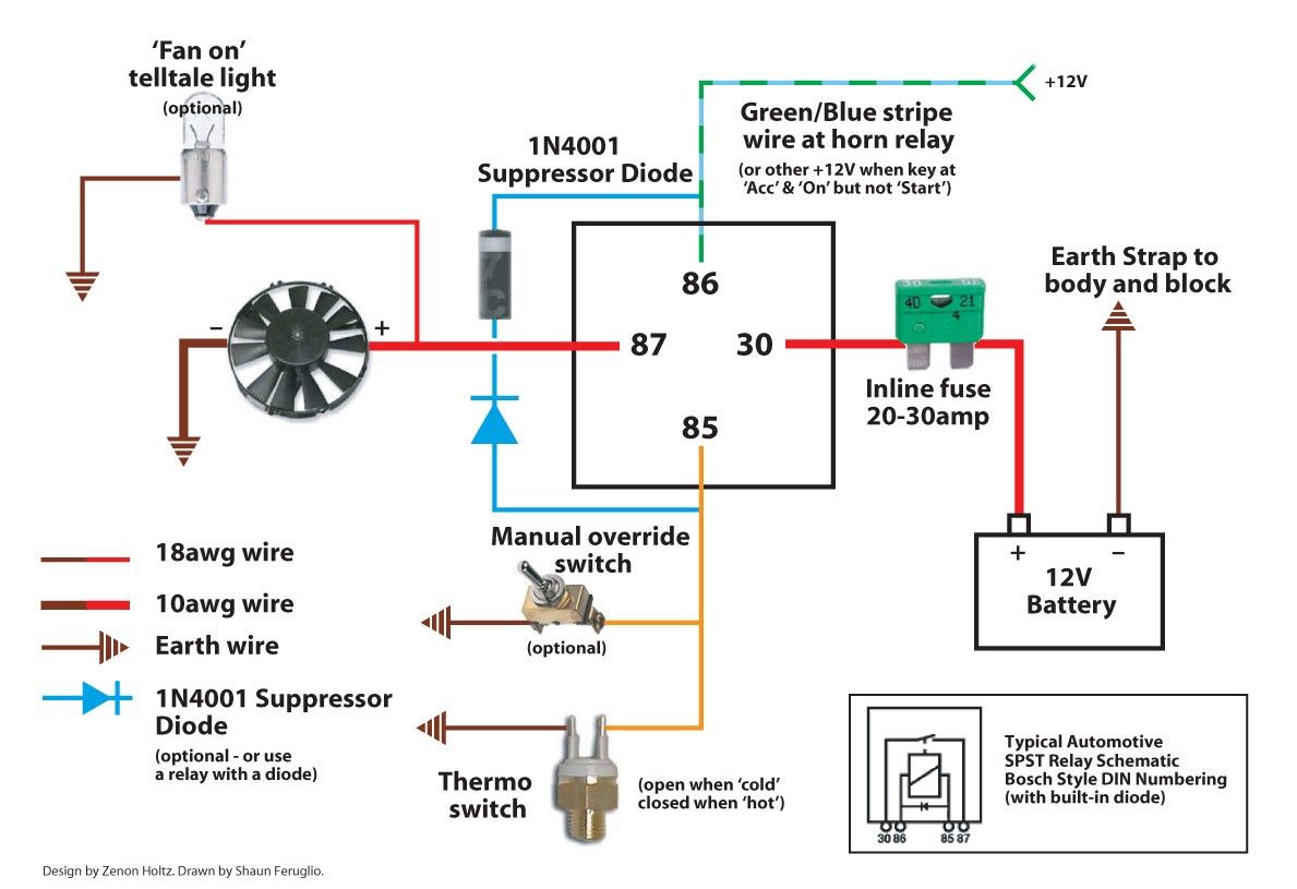
You can download a simplified example of an electric radiator fan wiring diagram to get started. It provides a visual guide to complement the content of this article. Please use it as a learning tool, and consult the specific wiring diagram for your vehicle when undertaking any actual repairs. The linked diagram is available here: Generic Electric Radiator Fan Wiring Diagram