
Electrical Connectors Automotive Wiring
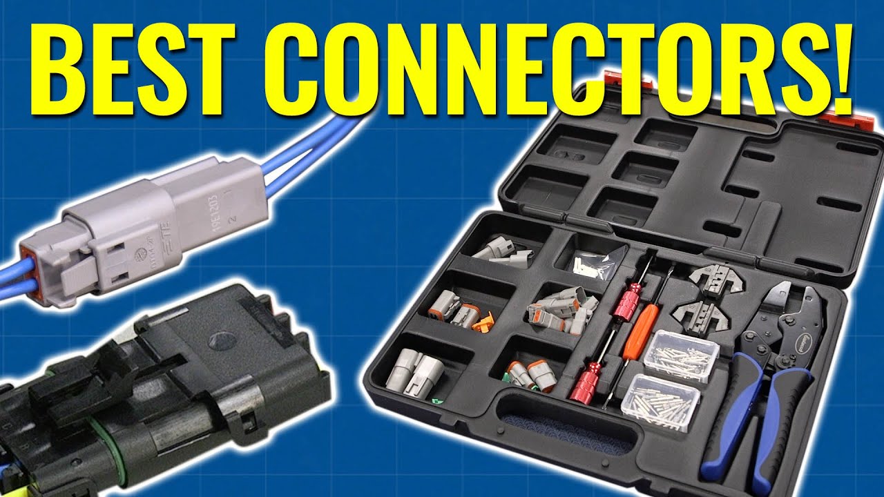
Alright, let's dive into the fascinating, and sometimes frustrating, world of automotive electrical connectors and wiring. Understanding this stuff is crucial whether you're chasing down a parasitic draw, installing a killer aftermarket sound system, or just trying to fix a flickering headlight. This knowledge empowers you to diagnose and repair electrical problems yourself, saving you a ton of money and time at the shop. We'll break down the anatomy of a typical automotive wiring system and connector types so you can feel confident tackling your next project.
Purpose of Understanding Automotive Wiring Diagrams and Connectors
Why bother learning about this? Well, think of it this way: your car's electrical system is its nervous system. Everything relies on it. A solid understanding of wiring diagrams and connectors gives you the power to:
- Diagnose Electrical Issues: Pinpoint the source of shorts, opens, and other electrical malfunctions.
- Perform Repairs Safely: Know which wires to cut, splice, and connect without risking damage or injury.
- Install Aftermarket Accessories: Add that new stereo, alarm system, or lighting upgrade with confidence.
- Modify Your Vehicle: Customize your ride with custom wiring solutions for performance enhancements.
- Interpret Wiring Diagrams: Understand the language of schematics, making troubleshooting much easier.
- Avoid Costly Repairs: Potentially save hundreds or even thousands of dollars by fixing problems yourself.
Key Specs and Main Parts of Automotive Wiring
Automotive wiring systems aren't as simple as household wiring. Here's what you need to know:
Wire Gauge (AWG)
The American Wire Gauge (AWG) is a standardized system for measuring wire diameter. The lower the AWG number, the thicker the wire and the more current it can safely carry. Common automotive wire gauges are 10, 12, 14, 16, 18, and 20 AWG. Higher current circuits, like starters and alternators, use thicker wires (lower AWG) than low-current circuits like dome lights.
Wire Insulation
The insulation around the wire protects it from shorting out against the vehicle's chassis and other components. Automotive wiring typically uses PVC (Polyvinyl Chloride) or cross-linked polyethylene (XLPE) insulation. XLPE is more heat-resistant and durable, often found in engine compartments.
Connectors
Connectors provide a secure and reliable way to join wires together. They come in various shapes, sizes, and pin configurations. Weatherpack connectors are common for exterior applications due to their environmental sealing. Delphi Metri-Pack connectors offer excellent vibration resistance. Other types include bullet connectors, spade connectors, and ring terminals. Connectors are designed with a locking mechanism to prevent accidental disconnection, especially in high vibration environments.
Fuses and Circuit Breakers
These are crucial safety devices that protect the wiring from overcurrent situations. Fuses are one-time-use devices, while circuit breakers can be reset. They are rated in Amperes (Amps), indicating the maximum current they can handle before interrupting the circuit.
Grounding
Proper grounding is essential for a functioning electrical system. The vehicle's chassis serves as a common ground point. Wires are connected to the chassis at various points to provide a return path for the current. Poor grounding can cause all sorts of strange electrical problems.
Understanding Wiring Diagram Symbols
Wiring diagrams are like roadmaps for your car's electrical system. Learning to read them is key. Here's a breakdown of common symbols:
- Lines: Represent wires. Thicker lines often indicate higher current-carrying capacity.
- Colors: Each wire is typically identified by a color code (e.g., red for power, black for ground, etc.). Color codes vary by manufacturer, so always refer to the specific diagram for your vehicle.
- Circles: Can represent various components, depending on what’s inside.
- Rectangles: Usually represent devices like relays, switches, or control modules.
- Zigzag Lines: Indicate resistors or other components that impede current flow.
- Ground Symbols: Indicate a connection to the vehicle's chassis ground.
- Connector Symbols: Show the location and type of connectors, often with pin numbers indicated.
Example: A solid line with "RD/BK" next to it means a red wire with a black stripe.
How It Works: A Simplified Circuit
Let's consider a simple circuit: a headlight. The circuit starts at the battery (+ terminal), flows through a fuse, then to the headlight switch. When the switch is turned on, the current flows through the headlight bulb, causing it to illuminate. From the bulb, the current returns to the battery through a ground connection to the vehicle's chassis. This completes the circuit.
In a wiring diagram, you'd see a line representing the wire from the battery to the fuse, another line from the fuse to the switch, and so on. The diagram would also show the color codes of the wires, the fuse rating, and the location of the ground connection.
Real-World Use: Basic Troubleshooting
Let's say your headlight isn't working. Here's how you might use your knowledge of wiring and connectors:
- Check the Bulb: Obvious, but always start with the easy stuff.
- Check the Fuse: Use a multimeter to check for continuity across the fuse. A blown fuse means a short circuit or overcurrent condition. Replace the fuse with one of the same rating. If it blows again, you have a problem to investigate.
- Check the Switch: Use a multimeter to check if the switch is working correctly. With the switch in the "on" position, there should be continuity between the input and output terminals.
- Check the Wiring and Connectors: Look for damaged, corroded, or loose wires and connectors. Pay particular attention to ground connections. Clean corroded connectors with electrical contact cleaner.
- Use a Wiring Diagram: Consult the wiring diagram for your vehicle to trace the circuit and identify potential problem areas.
Safety First: Risky Components
Working with automotive electrical systems can be dangerous. Always keep these safety tips in mind:
- Disconnect the Battery: Always disconnect the negative battery terminal before working on any electrical components. This prevents accidental shorts and potential shocks.
- Use Proper Tools: Use insulated tools specifically designed for electrical work.
- Avoid Working in Wet Conditions: Water conducts electricity. Never work on electrical systems in wet conditions.
- Be Careful with Airbags: Airbag systems are electrically triggered. Consult your vehicle's service manual before working near airbag components. Accidentally triggering an airbag can cause serious injury.
- High Voltage Components: Be aware of high-voltage components like ignition coils and some hybrid vehicle systems. These can deliver a dangerous electrical shock.
- Proper Fuse Replacement: Never replace a fuse with one of a higher amperage rating. This can overload the wiring and cause a fire.
High-energy ignition (HEI) systems, especially older ones, can store a significant charge even after the engine is turned off. Be extremely cautious when working around these systems.
Troubleshooting complex electrical issues requires a systematic approach, a multimeter, and a good understanding of your vehicle's wiring diagrams. Don't be afraid to take your time and double-check your work.
Now that you've got a solid foundation in automotive wiring, you're well-equipped to tackle a variety of electrical projects and repairs. Good luck, and stay safe!
We have a comprehensive wiring diagram available for download. This diagram can be invaluable for troubleshooting and understanding the electrical system of your vehicle.