Electrical Wiring Harness Connectors
So, you're diving into the world of automotive electrical systems? Smart move. Understanding wiring harnesses and, more importantly, their connectors, is crucial for everything from basic repairs to complex modifications. This article is your deep dive into the heart of these connections, arming you with the knowledge you need to tackle electrical projects with confidence. We'll be focusing on the connectors – the unsung heroes that make everything work (or not work!).
Purpose: Why Connector Knowledge Matters
Why should you bother learning about these seemingly insignificant plastic bits? The reasons are numerous. First and foremost, repairing electrical problems often means diagnosing issues at the connector level. Corroded terminals, loose connections, and broken locking mechanisms can all lead to frustrating malfunctions. Being able to identify, test, and repair these connectors is essential. Second, for those of you into modding and customization, understanding connectors allows you to safely and effectively integrate new components into your vehicle's electrical system. This prevents shorts, blown fuses, and, worse, electrical fires. Finally, even if you're just trying to learn about your car's inner workings, grasping the role of connectors provides a deeper understanding of how the entire electrical system is designed and functions. Think of them as the puzzle pieces that hold the electrical story together.
Key Specs and Main Parts
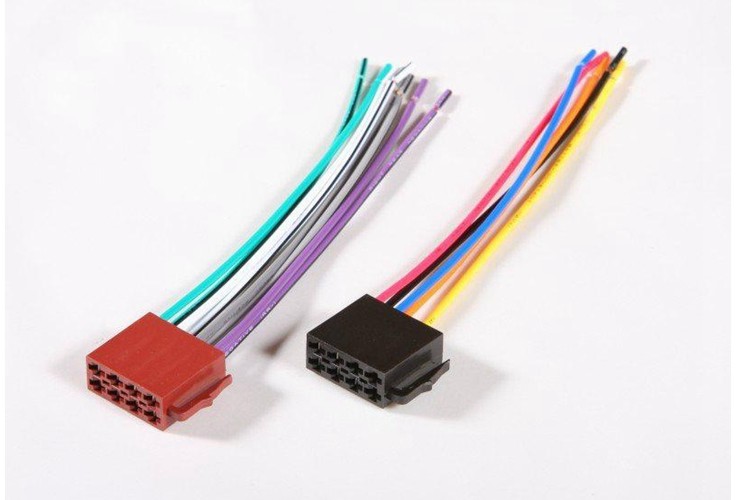
Let's break down the anatomy of a typical automotive wiring harness connector. While designs vary, most share common features:
- Connector Housing: This is the plastic body that holds everything together. It's often made from a durable, heat-resistant polymer. The housing provides physical protection for the terminals and incorporates features like locking tabs.
- Terminals: These are the metal contacts that make the electrical connection. They're typically made from brass or copper alloys and are often plated with tin or gold to resist corrosion and improve conductivity. Terminals come in various shapes and sizes depending on the wire gauge and current rating. Common types include blade, pin, and socket terminals.
- Wire Seals: These are rubber or silicone seals that fit around the wires where they enter the connector housing. Their purpose is to prevent moisture and contaminants from entering the connector and causing corrosion.
- Locking Mechanism: Most connectors have a locking mechanism to ensure a secure and reliable connection. This can be a simple clip or a more complex latching system. These mechanisms prevent the connector from vibrating loose over time.
- TPA (Terminal Position Assurance): Some connectors include a TPA, a secondary locking feature that ensures the terminals are fully seated and locked in place within the housing.
Key specifications to consider when dealing with connectors include:
- Current Rating: This is the maximum amount of current the connector can safely handle. Exceeding this rating can lead to overheating and failure.
- Voltage Rating: This is the maximum voltage the connector can safely handle.
- Wire Gauge Range: This specifies the range of wire sizes the connector is designed to accommodate.
- Operating Temperature: This indicates the temperature range in which the connector will function reliably.
- Ingress Protection (IP) Rating: This indicates the connector's resistance to dust and water. A higher IP rating means better protection.
Symbols: Decoding the Electrical Language
While we aren't diving directly into full circuit diagrams, understanding some basic symbols associated with connectors is helpful. Circuit diagrams often represent connectors as simple rectangles or circles with numbered pins. Lines represent wires connecting to these pins. Here's a breakdown:
- Solid Lines: Indicate a direct wired connection.
- Dashed Lines: May represent shielded wiring or a connection behind the physical representation shown.
- Colors: Wiring diagrams use color codes to identify individual wires within the harness. Common colors include red (power), black (ground), yellow, green, blue, white, and brown. Sometimes, wires will have tracer colors (a stripe) to further differentiate them. For example, a wire might be "Red/White," meaning a red wire with a white stripe.
- Numbering/Lettering: Pins and terminals within the connector are often labeled with numbers or letters to identify their specific function. These labels are crucial for troubleshooting and making accurate connections. Always refer to the vehicle's wiring diagram for accurate pin assignments.
- Connector Gender: Male connectors (with pins) are often represented differently than female connectors (with sockets). This distinction is important for visually identifying the correct mating connector.
Understanding these symbols allows you to trace circuits, identify connection points, and troubleshoot electrical problems more effectively.
How It Works: The Connection Process
The basic principle is simple: a metal terminal in one connector makes physical contact with a mating terminal in another connector, allowing electrical current to flow. However, achieving a reliable connection requires more than just metal-to-metal contact. Here's a simplified overview:
- Wire Preparation: The wire is stripped to expose the conductor (usually copper).
- Terminal Crimping: The terminal is crimped onto the exposed conductor using a specialized crimping tool. A proper crimp creates a gas-tight seal between the terminal and the wire, ensuring a low-resistance connection. Improper crimping is a leading cause of connector failure.
- Terminal Insertion: The crimped terminal is inserted into the connector housing. The locking mechanism within the housing secures the terminal in place.
- Connector Mating: The two connector halves are aligned and pushed together until the locking mechanism engages, creating a secure and reliable electrical connection.
The pressure applied by the locking mechanism helps to maintain good contact between the terminals, even under vibration and temperature changes.
Real-World Use: Basic Troubleshooting Tips
Connectors are often the source of electrical problems. Here are some common troubleshooting tips:
- Visual Inspection: Start by visually inspecting the connector for signs of damage, corrosion, or loose wires. Look for cracks in the housing, discolored terminals, and frayed wires.
- Continuity Testing: Use a multimeter to test for continuity between the terminals on either side of the connector. A lack of continuity indicates a broken wire or a corroded terminal. Remember to disconnect the power source before testing!
- Voltage Testing: Use a multimeter to check for voltage at the connector. This can help you determine if power is reaching the component.
- Connector Cleaning: If the terminals are corroded, clean them with a wire brush or a specialized electrical contact cleaner.
- Terminal Repair: If a terminal is damaged, it may need to be replaced. This requires specialized tools and techniques.
- Wiring Harness Repair: If the wiring harness is damaged then it may need to be spliced.
- Pay attention to diagnostic trouble codes (DTCs): Many DTCs will refer to specific circuits and components, often leading you directly to the relevant connector.
Example: Let's say your headlights are not working, and you suspect a connector issue. First, check the headlight connectors for any obvious damage or corrosion. Then, use a multimeter to test for voltage at the connector when the headlights are switched on. If there's no voltage, trace the wiring back to the headlight switch or fuse box, checking other connectors along the way.
Safety: Handle with Care
Working with automotive electrical systems can be dangerous. Here are some important safety precautions:
- Disconnect the Battery: Always disconnect the negative battery terminal before working on any electrical component. This prevents accidental shorts and electrical shocks.
- Avoid Working on Live Circuits: If you must work on a live circuit, use extreme caution. Wear insulated gloves and use insulated tools.
- Identify High-Voltage Components: Be aware of high-voltage components, such as the ignition system and hybrid/electric vehicle systems. These components can deliver a dangerous or even lethal electrical shock. Never tamper with high-voltage components unless you are properly trained and equipped.
- Use Proper Tools: Use the correct tools for the job, including crimping tools, wire strippers, and multimeters.
- Consult Wiring Diagrams: Always refer to the vehicle's wiring diagram before making any connections or repairs.
Specifically, pay close attention to the connectors associated with the following components:
- Airbag System: Disconnecting and reconnecting airbag connectors requires specific procedures to prevent accidental deployment.
- ABS (Anti-lock Braking System): Similar to airbags, improper handling of ABS connectors can cause system malfunctions.
- Engine Control Unit (ECU): The ECU is the brain of the engine, and its connectors are critical. Mishandling them can cause serious engine problems.
Remember, safety is paramount. If you're unsure about any aspect of the electrical system, consult a qualified mechanic.
That's a comprehensive overview of automotive wiring harness connectors! You now have a solid foundation for understanding, troubleshooting, and repairing these essential components.
We have an example wiring diagram available for download to further aid in your understanding. The downloadable file contains detailed information about connector types, pinouts, and wiring configurations. Feel free to reach out if you have any questions.