
Electrical Wiring Harnesses Automotive
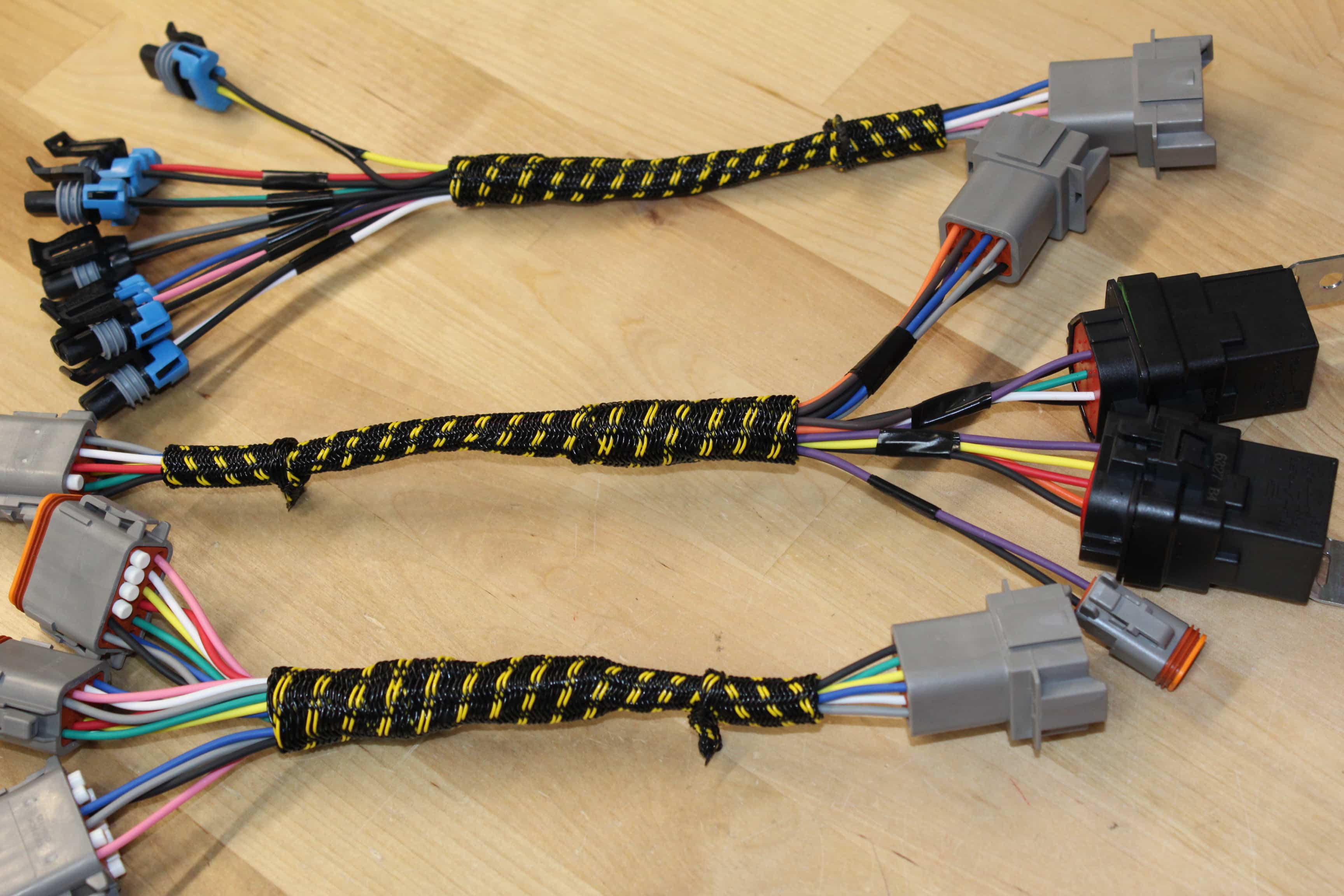
Electrical wiring harnesses are the unsung heroes of your car, the intricate network of nerves that allows all the different components to communicate and function. Think of them as the central nervous system, relaying commands from the driver to the engine, lights, sensors, and everything in between. Understanding automotive wiring harnesses is crucial for anyone undertaking repairs, modifications, or even just diagnosing electrical problems. This guide will break down the key aspects, making you more confident when tackling electrical projects on your vehicle. We have the detailed wiring diagrams available for download if you need them, just follow the link at the end.
Purpose and Importance
Why bother learning about wiring harnesses? The primary reason is troubleshooting electrical issues. From a simple blown fuse to a complex sensor malfunction, understanding the wiring diagram and how the harness is laid out can drastically reduce diagnostic time. Additionally, if you're planning modifications like installing aftermarket lights, audio systems, or performance upgrades, a solid understanding of the existing harness is indispensable to avoid creating short circuits, damaging components, or even causing a fire. Furthermore, if you are restoring an old car, you will almost certainly have to repair or replace sections of the harness.
Key Specifications and Main Parts
An automotive wiring harness is much more than just a bunch of wires bundled together. It's a carefully engineered system designed for reliability, durability, and ease of manufacturing. Here's a breakdown of the core components and considerations:
- Wires: The individual conductors carrying electrical current. Automotive wire is typically stranded copper, offering flexibility and vibration resistance. Wire gauge (AWG - American Wire Gauge) is critical; thicker wires (smaller AWG number) handle higher current loads. Using the wrong gauge can lead to overheating and potential fire hazards.
- Connectors: Connectors are used to join wires together and to connect the harness to various components. They come in various forms, including multi-pin connectors, bullet connectors, spade connectors, and ring terminals. They provide a secure and reliable electrical connection and are often keyed to prevent incorrect connections. Weatherproof connectors are crucial in areas exposed to the elements.
- Terminals: These are the metal contacts within the connectors that physically connect to the wires. They are crimped or soldered onto the wire ends to ensure a good electrical connection. Quality crimping is essential to avoid loose connections, which cause resistance, heat, and eventual failure.
- Protective Sleeving/Conduit: Wiring harnesses are typically encased in some form of protective sleeving or conduit. This protects the wires from abrasion, heat, moisture, and chemicals. Common materials include corrugated tubing, split loom tubing, heat shrink tubing, and electrical tape.
- Grounding Straps/Wires: A good ground connection is essential for proper electrical function. Grounding straps or wires connect the harness to the vehicle's chassis, providing a low-resistance path for current to return to the battery.
- Fuses and Relays: Fuses are safety devices designed to protect circuits from overcurrent. When the current exceeds the fuse's rating, the fuse melts, breaking the circuit. Relays are electromechanical switches that allow a low-current circuit to control a high-current circuit. They're often used to control lights, motors, and other high-power components.
Understanding Wiring Diagram Symbols
Wiring diagrams use standardized symbols to represent electrical components and connections. Learning to interpret these symbols is crucial for understanding the harness layout. Here's a brief overview:
- Lines: Lines represent wires. Solid lines typically indicate a direct connection, while dashed lines may represent shielded wires or signal paths. The thickness of the line doesn't usually represent wire gauge, but rather emphasizes the wire's importance or path.
- Colors: Wire colors are represented by abbreviations (e.g., BLU for Blue, RED for Red, GRN for Green, BLK for Black, WHT for White, YEL for Yellow). Often, wires have a primary color and a stripe color (e.g., BLU/WHT = Blue with a White stripe).
- Component Symbols: Each electrical component (resistors, capacitors, diodes, transistors, sensors, actuators) has a unique symbol. Consult the wiring diagram's legend for a complete list.
- Ground Symbols: Different ground symbols represent different types of grounding (e.g., chassis ground, engine ground).
- Connector Symbols: These represent the type of connector used to connect two wires together or connect the harness to components. Often, the diagram specifies the connector type and pin numbers.
How It Works: The Flow of Electricity
Understanding how electricity flows through a circuit is fundamental. In a basic circuit, electricity flows from the positive (+) terminal of the battery, through a wire, to a component (e.g., a light bulb), through another wire, and back to the negative (-) terminal of the battery. The harness provides the pathways for this flow. A wiring diagram shows the layout of these pathways, indicating which components are connected and how. The circuit must be complete for the component to function. An open circuit (broken wire or loose connection) prevents current flow, while a short circuit (current bypassing the intended path) can cause excessive current and damage.
Real-World Use: Basic Troubleshooting Tips
Here are a few basic troubleshooting tips you can use to diagnose common wiring harness problems:
- Visual Inspection: Always start with a thorough visual inspection. Look for obvious signs of damage, such as frayed wires, corroded connectors, melted insulation, or loose connections.
- Fuse Check: If a component isn't working, check its fuse. A blown fuse indicates an overcurrent situation that needs to be investigated. Replace the fuse with the correct amperage rating. If the new fuse blows immediately, there's likely a short circuit.
- Continuity Testing: Use a multimeter to check the continuity of wires and connections. Disconnect the battery before performing continuity tests. Continuity means there is a complete path for current flow. If there's no continuity, there's a break in the wire or a bad connection.
- Voltage Testing: Use a multimeter to check for voltage at various points in the circuit. This can help you determine if power is reaching the component.
- Ground Testing: Use a multimeter to check the ground connection. A good ground connection should have very low resistance (close to zero ohms) to the chassis.
Example: Your headlights aren't working. First, check the headlight fuse. If it's blown, replace it. If the new fuse blows immediately, there's a short circuit in the headlight circuit. Next, check the headlight relay. If the relay is good, use a multimeter to check for voltage at the headlight connector. If there's no voltage, trace the wiring back to the relay or fuse box, looking for breaks or bad connections. Ensure the headlight ground is solid.
Safety: Handling Risky Components
Working with electrical systems can be dangerous. Always take the following precautions:
- Disconnect the Battery: Always disconnect the negative (-) terminal of the battery before working on any electrical system. This prevents accidental short circuits and electrical shocks.
- Use Proper Tools: Use insulated tools designed for electrical work.
- Avoid Working in Wet Conditions: Never work on electrical systems in wet conditions.
- Be Aware of Airbags: Airbag systems contain explosive charges. Disconnect the battery and wait at least 30 minutes before working near airbag components. Consult the vehicle's service manual for specific instructions.
- High-Voltage Components: Be extremely cautious when working with high-voltage components, such as the ignition system or hybrid/electric vehicle systems. These systems can deliver lethal shocks.
Specifically, never probe or pierce wires to test for voltage. This damages the insulation and can create future problems. Use back probing techniques or connector test leads to safely access wires.
Remember that diagnosing complex electrical problems can be challenging. If you're not comfortable working with electrical systems, consult a qualified mechanic.
Now that you have a better understanding of automotive wiring harnesses, you're better equipped to tackle repairs, modifications, and diagnostics. And for your convenience, we have a detailed wiring diagram available for download. Click HERE (This is a placeholder, insert your download link here) to download the file and further your knowledge.