Electronic Ignition Distributor Wiring Diagram
Understanding the electronic ignition distributor wiring diagram is crucial for anyone tackling engine maintenance, modifications, or troubleshooting ignition-related issues on older vehicles. It's the roadmap to a functional and reliable spark, ultimately ensuring your engine runs smoothly. This article will break down the diagram, its components, and how to effectively use it, even if you're not a seasoned mechanic.
Purpose of the Electronic Ignition Distributor Wiring Diagram
The diagram's primary purpose is to provide a clear and concise visual representation of the electrical connections within the electronic ignition system. It details how each component is wired, enabling you to:
- Diagnose faults: Quickly identify broken or misconnected wires, short circuits, or open circuits.
- Perform repairs: Accurately reconnect wires after repairs or replacements.
- Understand system operation: Gain a deeper understanding of how the ignition system works.
- Retrofit or modify systems: Safely install aftermarket ignition systems or modify existing ones.
Without a proper diagram, working on an ignition system is like navigating a maze blindfolded – you're likely to cause more harm than good.
Key Specifications and Main Parts
Before diving into the diagram itself, let's identify the key components and specifications typically found in an electronic ignition distributor system:
Main Components:
- Distributor: The central component, housing the ignition module, pickup coil (also known as a trigger coil or magnetic pulse generator), and sometimes a centrifugal advance mechanism and/or a vacuum advance unit. It distributes the high-voltage spark to the correct cylinder at the correct time.
- Ignition Module (Ignition Control Unit - ICU): This is the electronic brain of the system. It receives signals from the pickup coil and controls the ignition coil's primary circuit, determining when to create the spark.
- Ignition Coil: A transformer that steps up the 12V battery voltage to the high voltage (typically 20,000 to 40,000 volts) needed to create a spark across the spark plug gap.
- Pickup Coil (Trigger Coil): Generates a signal when the distributor shaft rotates and a magnetic reluctor passes by it. This signal triggers the ignition module to fire the spark.
- Spark Plugs: The final destination of the high-voltage spark, igniting the air-fuel mixture in the cylinders.
- Ballast Resistor (or Resistance Wire): Used in some older systems to reduce the voltage to the ignition coil after the engine starts, prolonging coil life. Modern systems often integrate this function into the ignition module.
- Battery: Provides the 12V power source for the entire ignition system.
- Wiring Harness: The network of wires connecting all the components.
Key Specifications:
- Voltage: Typically 12V DC (Direct Current).
- Coil Primary Resistance: Measured in Ohms (Ω). This value is critical for compatibility with the ignition module. Using a coil with the wrong resistance can damage the module.
- Coil Secondary Resistance: Also measured in Ohms (Ω), but much higher than the primary resistance.
- Pickup Coil Resistance: Measured in Ohms (Ω).
- Dwell Angle: The number of degrees of distributor rotation that the ignition coil's primary circuit is switched on. Modern electronic ignition systems often control dwell automatically.
- Timing Advance: The amount of advance (in degrees) that the ignition timing is adjusted based on engine speed (centrifugal advance) and/or engine load (vacuum advance).
Symbols – Understanding the Wiring Diagram Language
Wiring diagrams use standardized symbols to represent electrical components and connections. Understanding these symbols is essential for interpreting the diagram:
Lines:
- Solid lines: Represent wires. The thickness of the line doesn't usually indicate wire gauge, but rather distinguishes between power carrying wires and signal carrying wires.
- Dashed lines: May represent shielding or grounding connections.
- Arrows on lines: Indicate the direction of current flow (although conventional current flow is shown – positive to negative).
Colors:
Each wire is typically assigned a specific color, indicated by abbreviations (e.g., BLK for black, RED for red, GRN for green, YEL for yellow, BLU for blue, WHT for white). Colors are critical for tracing wires and ensuring correct connections.
Icons:
- Battery: Represented by a series of long and short parallel lines.
- Resistor: Represented by a jagged line.
- Capacitor: Represented by two parallel lines.
- Ground: Represented by a series of lines decreasing in size or a triangle pointing downwards.
- Coil: Represented by a series of loops.
- Switch: Represented by a break in a line with a lever arm.
- Diode: Represented by a triangle pointing to a vertical line.
- Fuse: Represented by a zigzag line inside a rectangle.
Additionally, many diagrams will include connector callouts – small circles or squares with numbers indicating which connector and pin number a wire connects to.
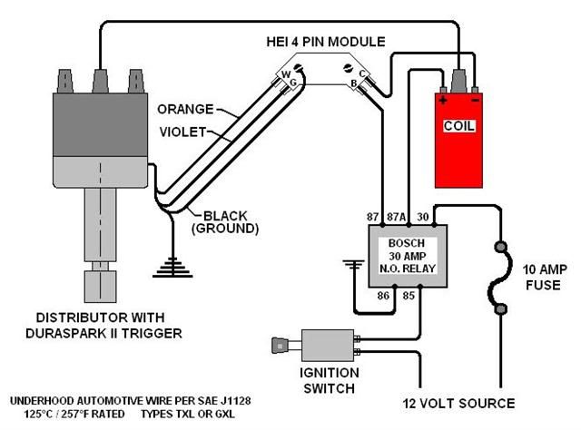
How It Works: Following the Electrical Path
Let's trace the electrical path through a typical electronic ignition system:
- Power Source: The system receives power from the battery, typically through the ignition switch.
- Ignition Switch: When the ignition switch is turned to the "run" or "start" position, power is supplied to the ignition module.
- Pickup Coil Signal: As the engine rotates, the reluctor on the distributor shaft passes by the pickup coil, generating a small AC voltage signal.
- Ignition Module Processing: The ignition module receives this signal and determines the precise moment to fire the spark. It then switches the primary circuit of the ignition coil on and off.
- Coil Charging and Discharge: When the ignition module switches the coil's primary circuit on, current flows through the coil, building up a magnetic field. When the module switches the circuit off, the magnetic field collapses rapidly. This rapid collapse induces a high-voltage surge in the coil's secondary winding.
- Distributor Distribution: The high-voltage surge is then directed to the correct spark plug by the distributor rotor and cap.
- Spark Plug Ignition: The high-voltage spark jumps across the spark plug gap, igniting the air-fuel mixture in the cylinder.
Real-World Use – Basic Troubleshooting Tips
The wiring diagram is invaluable for troubleshooting ignition problems. Here are a few basic tips:
- No Spark: If there's no spark at any of the spark plugs, check for power to the ignition module and coil. Use a multimeter to verify voltage and ground connections. Also check the coil primary resistance.
- Weak Spark: A weak spark can be caused by a faulty ignition coil, a bad pickup coil, or a weak battery.
- Intermittent Spark: Intermittent spark can be caused by loose wiring connections, a faulty ignition module, or a cracked distributor cap.
- Incorrect Timing: Check the distributor timing using a timing light. If the timing is off, adjust the distributor accordingly.
- Using a Multimeter: Familiarize yourself with using a multimeter to check for voltage, continuity, and resistance. These are your primary tools for electrical diagnostics.
Always compare your readings to the specifications in your vehicle's service manual or online resources. Remember to disconnect the negative battery cable before performing any electrical work.
Safety – Respect the High Voltage!
The ignition system generates extremely high voltages that can be dangerous or even fatal.
- Never touch spark plug wires or the ignition coil while the engine is running.
- Always disconnect the negative battery cable before working on the ignition system.
- Be careful when testing spark plugs. Use insulated tools and avoid touching the spark plug electrode or the surrounding metal.
- Do not bypass safety features like ballast resistors or fusible links without proper understanding and precautions.
Working on the ignition system requires caution and respect for the high voltages involved. If you're unsure about any procedure, consult a qualified mechanic.
The electronic ignition distributor wiring diagram is your essential guide to understanding, maintaining, and troubleshooting your vehicle's ignition system. With a clear understanding of the components, symbols, and electrical paths, you can confidently tackle ignition-related repairs and modifications.
We have a high-resolution, printable version of a generic electronic ignition distributor wiring diagram available for download. Contact us for the download link.