
Emergency Brake Parking Brake Diagram
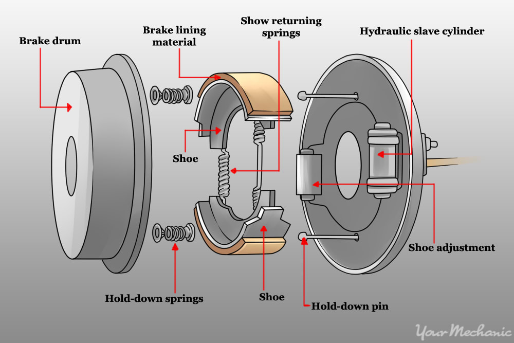
Whether you're performing routine maintenance, troubleshooting a brake issue, or customizing your vehicle, understanding the emergency brake (or parking brake) system is crucial. This article provides a comprehensive look at the emergency brake parking brake diagram, breaking down its components, function, and how to interpret it like a seasoned mechanic.
Why Understanding the Emergency Brake Diagram Matters
The emergency brake system is a critical safety feature, and its proper functioning can be the difference between a minor inconvenience and a major accident. A diagram helps you:
- Diagnose Problems: Accurately identify the source of issues like a loose cable, seized components, or malfunctioning actuators.
- Perform Repairs: Guide you through replacing parts, adjusting cable tension, and ensuring correct assembly.
- Customize and Modify: Assist in installing aftermarket handbrakes, upgrading cables, or adapting the system for specific driving needs.
- Learn Vehicle Systems: Deepen your understanding of how the emergency brake interacts with the overall braking system and vehicle chassis.
Key Specs and Main Parts
Before diving into the diagram itself, let's define the core components of a typical emergency brake system:
- Actuator (Lever or Pedal): The mechanism you engage to apply the brake. This can be a hand lever, a foot pedal, or, in some modern cars, an electronic button.
- Cables: Steel cables that transmit the force from the actuator to the brakes. The number of cables can vary depending on the vehicle. Some systems use a single cable split into two, while others have individual cables for each wheel.
- Equalizer: A device that distributes the force evenly between the left and right brakes. This ensures that both wheels lock up with equal pressure, preventing the car from pulling to one side.
- Brake Shoes or Pads: Friction materials that press against the brake drums or rotors to create stopping force. In drum brake systems, shoes are used. In disc brake systems, a separate small drum brake or the main disc brake pads are used by the emergency brake.
- Drums or Rotors: The rotating components that the brake shoes or pads press against.
- Springs and Linkages: Various springs and linkages that assist in applying and releasing the brake, ensuring proper return to the disengaged position.
Understanding Diagram Symbols
The diagram utilizes standardized symbols to represent different components. Understanding these symbols is crucial for accurate interpretation.
- Solid Lines: Typically represent mechanical linkages or cables. Thicker lines often indicate main cables or load-bearing components.
- Dashed Lines: Can represent hydraulic lines (if the emergency brake utilizes a hydraulic booster), electrical wiring (for electronic parking brakes), or control linkages.
- Circles: Often used to represent pivots, joints, or pulleys. The filling of the circle can sometimes indicate the type of joint (e.g., a solid fill for a fixed joint).
- Rectangles: Can represent various components, such as the actuator, equalizer, or electronic control modules. The internal markings of the rectangle provide further detail about its function.
- Spring Symbols: Represent springs. The direction of the spring indicates whether it is a compression or extension spring.
- Arrows: Indicate the direction of force or movement.
- Colors (If Present): Colors might be used to differentiate between different circuits or types of components. For example, a blue line might indicate a hydraulic line, while a red line might indicate an electrical power wire.
Important: The specific symbols used can vary slightly depending on the manufacturer and the year of the vehicle. Always refer to the legend or key provided with the diagram for accurate identification.
How It Works: From Lever to Locked Wheels
The operation of a typical emergency brake system is relatively straightforward:
- Engagement: You engage the actuator (lever or pedal). This action pulls on the main brake cable.
- Force Transmission: The main cable transmits the pulling force to the equalizer.
- Force Distribution: The equalizer distributes the force evenly to the left and right brake cables.
- Brake Application: The individual brake cables pull on levers or mechanisms at each wheel. These levers actuate the brake shoes or pads, pressing them against the drums or rotors.
- Wheel Locking: The friction between the shoes/pads and the drums/rotors creates a braking force, eventually locking the wheels.
- Disengagement: Releasing the actuator slackens the cables. Return springs at the brakes pull the shoes/pads away from the drums/rotors, releasing the brakes.
In modern vehicles with electronic parking brakes, the actuator is an electronic switch. This switch sends a signal to a control module, which then activates electric motors to pull the brake cables or directly apply the brakes at each wheel. These systems often incorporate sophisticated sensors to monitor brake application and prevent over-tightening.
Real-World Use: Basic Troubleshooting
Here are some basic troubleshooting tips, keeping the diagram in mind:
- Loose Lever/Pedal: Check the cable tension. A loose cable might indicate stretching, fraying, or detachment at one of the connection points. The diagram will show you the cable routing and connection points.
- Uneven Braking: This can be caused by a malfunctioning equalizer or unequal cable tension. Use the diagram to locate the equalizer and visually inspect it for damage or binding. Adjust cable tension according to the vehicle's service manual.
- Brake Not Releasing: Could be due to seized cables, corroded linkages at the wheels, or weak return springs. Refer to the diagram to identify the linkages and springs. Lubricate or replace as needed. In electronic systems, check for error codes and consult the vehicle's diagnostic manual.
- Grinding Noises: Often indicates worn brake shoes or pads. Disassemble the brake assembly at the wheel. The diagram will guide you on the proper disassembly and reassembly procedures.
Safety First: Risky Components
Working on the brake system involves inherent risks. Consider these safety precautions:
- Eye Protection: Always wear safety glasses when working under the vehicle to protect your eyes from debris.
- Gloves: Protect your hands from grease, oil, and sharp edges.
- Wheel Chocks: Use wheel chocks to prevent the vehicle from rolling while you are working on the brakes.
- Jack Stands: Never work under a vehicle supported only by a jack. Use sturdy jack stands.
- Brake Dust: Brake dust can contain asbestos (especially in older vehicles). Avoid breathing in brake dust. Use a brake cleaner designed to minimize dust and wear a respirator if necessary.
- Cable Tension: Be cautious when adjusting cable tension. Over-tightening can damage the cables or brake components. Always follow the manufacturer's specifications.
- Spring Tension: Some brake components are held in place by strong springs. Use the correct tools to safely remove and install these springs to avoid injury.
- Electronic Systems: Exercise extreme caution when working on vehicles with electronic parking brakes. Disconnect the battery before working on the electrical components. Refer to the vehicle's service manual for specific safety precautions.
By understanding the emergency brake parking brake diagram, you can gain a deeper understanding of this critical safety system. Remember to always prioritize safety and consult the vehicle's service manual for specific instructions and torque specifications.
We have a detailed diagram available for download. Contact us for access.