Engine 3.8 Gm Vacuum Line 3800 Series 2 Vacuum Diagram
Alright, let's dive into the fascinating world of vacuum lines on your 3.8L GM 3800 Series II engine. This article will serve as your comprehensive guide to understanding the vacuum system, interpreting its diagram, and tackling common issues you might encounter. Whether you're chasing down a pesky lean code, planning some performance upgrades, or simply want to deepen your automotive knowledge, understanding this system is crucial.
Purpose of a Vacuum Diagram
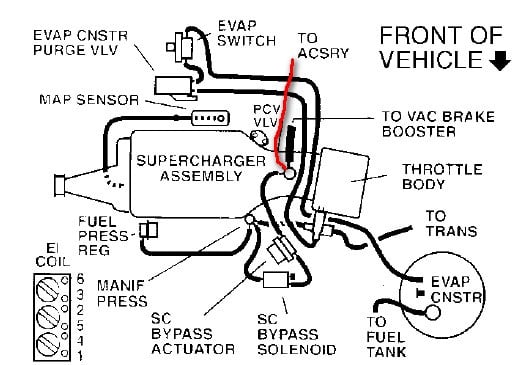
The vacuum diagram for your 3800 Series II engine is essentially a roadmap of the entire vacuum system. It depicts how various components are interconnected via vacuum hoses, showing the routing, connection points, and sometimes even the specific type of hose used. This information is invaluable for several reasons:
- Diagnosis and Repair: A vacuum leak can cause a multitude of problems, from rough idling and poor fuel economy to driveability issues and illuminated check engine lights. The diagram allows you to pinpoint the source of the leak quickly by visually tracing the hoses and identifying potential problem areas.
- Maintenance: Vacuum hoses deteriorate over time, becoming brittle and prone to cracking. Using the diagram, you can systematically inspect and replace old or damaged hoses, preventing future problems.
- Modification: If you're adding performance parts, such as a supercharger or turbocharger (although less common on the 3800), you'll likely need to modify the vacuum system. The diagram will help you understand the existing setup and plan your modifications accordingly.
- Learning and Understanding: Even if you're not actively working on your car, studying the diagram can deepen your understanding of how the engine's systems interact. You'll gain insight into the function of various components and their relationship to engine performance.
Key Specs and Main Parts
The 3.8L 3800 Series II engine relies on vacuum for the operation of numerous components. Let's break down the key players:
- Intake Manifold: This is the primary source of vacuum. The negative pressure created by the pistons drawing air into the cylinders is harnessed from the intake manifold.
- Vacuum Hoses: These flexible tubes are the arteries of the system, connecting the intake manifold to various components. They come in different sizes and materials to withstand the harsh engine environment.
- PCV Valve (Positive Crankcase Ventilation): This valve regulates the flow of crankcase gases back into the intake manifold for combustion. A faulty PCV valve or leaking hoses connected to it is a very common source of vacuum leaks.
- EGR Valve (Exhaust Gas Recirculation): This valve reduces emissions by recirculating a portion of the exhaust gas back into the intake manifold. It's vacuum-operated, meaning it opens and closes based on engine vacuum.
- EVAP System (Evaporative Emission Control): This system captures fuel vapors from the fuel tank and prevents them from being released into the atmosphere. It uses vacuum to purge these vapors into the engine for combustion. Key components include the canister purge valve, vent solenoid, and charcoal canister.
- Brake Booster: This assists the driver in applying the brakes by using engine vacuum to amplify the force applied to the brake pedal. A large diameter hose connects the booster to the intake manifold.
- MAP Sensor (Manifold Absolute Pressure): While not directly *operated* by vacuum, the MAP sensor *measures* intake manifold pressure, providing crucial data to the PCM (Powertrain Control Module) for fuel and ignition timing calculations. Changes in vacuum directly affect MAP sensor readings.
- HVAC System: Vacuum often controls the various flaps and doors inside the HVAC system, directing airflow to different vents.
- Vacuum Reservoir: A small tank that stores vacuum for use when the engine isn't producing enough, especially during hard acceleration. This helps maintain consistent operation of vacuum-dependent accessories.
Symbols and Diagram Interpretation
Understanding the symbols used in the vacuum diagram is essential for proper interpretation. Here's a breakdown of common symbols:
- Solid Lines: Typically represent vacuum hoses. The thickness of the line might indicate the hose diameter.
- Dotted Lines: Often indicate control signals or electrical connections within the vacuum system (e.g., wiring to a solenoid).
- Arrows: Indicate the direction of airflow.
- Color Coding: Some diagrams use color coding to differentiate between different types of hoses or systems. Consult the specific diagram for your vehicle to understand the color scheme.
- Component Symbols: Each component (PCV valve, EGR valve, canister purge valve, etc.) is represented by a specific symbol. These symbols are usually labeled.
- Connectors/T-Fittings: These are points where vacuum hoses connect to each other or to components. Pay close attention to these areas, as they are common sources of leaks.
Pay close attention to any notes or legends provided with the diagram. These often contain important information about hose sizes, routing variations, and specific component details.
How It Works
The 3800 Series II engine generates vacuum in the intake manifold during the intake stroke. This vacuum is then distributed through a network of hoses to various components that rely on it for their operation. For example:
- The PCV system uses vacuum to draw crankcase gases out of the engine, preventing pressure buildup and removing harmful contaminants.
- The EGR valve uses vacuum to open and allow exhaust gas to recirculate into the intake manifold, reducing NOx emissions.
- The EVAP system uses vacuum to purge fuel vapors from the charcoal canister, preventing them from being released into the atmosphere.
- The brake booster uses vacuum to assist the driver in applying the brakes, making it easier to stop the vehicle.
The PCM (Powertrain Control Module) controls many of these systems by regulating the flow of vacuum to the components. Solenoid valves, for example, are often used to switch vacuum on and off to control the EGR valve or the canister purge valve. The PCM makes these decisions based on inputs from various sensors, such as the MAP sensor and engine speed.
Real-World Use – Basic Troubleshooting Tips
Vacuum leaks can be tricky to diagnose, but here are some basic troubleshooting tips:
- Visual Inspection: Carefully inspect all vacuum hoses for cracks, breaks, or signs of deterioration. Pay close attention to the ends of the hoses, where they connect to components.
- Listening Test: With the engine running, listen for a hissing sound near vacuum hoses and components. This can indicate a vacuum leak.
- Smoke Test: A smoke test is a highly effective way to find vacuum leaks. A smoke machine injects a dense smoke into the vacuum system, and any leaks will be readily apparent.
- Brake Cleaner/Carb Cleaner Method: (Use with extreme caution!) Briefly spraying a small amount of brake cleaner or carb cleaner around vacuum hoses and components can help identify leaks. If the engine speed changes when you spray a particular area, it indicates a vacuum leak in that area. Be very careful not to spray cleaner near hot exhaust components, as this can cause a fire. Work in a well-ventilated area.
- Using a Vacuum Gauge: Connect a vacuum gauge to a vacuum port on the intake manifold. A low or erratic vacuum reading can indicate a leak or other engine problem.
Safety
Working with vacuum lines generally isn't inherently dangerous, but there are a few precautions to keep in mind:
- Hot Components: Be careful when working near hot exhaust components or the engine block. Allow the engine to cool down before working on the vacuum system.
- Flammable Liquids: As mentioned before, using flammable liquids like brake cleaner or carb cleaner to find leaks can be dangerous. Use them sparingly and with extreme caution. Keep a fire extinguisher nearby.
- Proper Tools: Use the correct tools for removing and installing vacuum hoses. Using pliers or other improper tools can damage the hoses or the components they connect to.
- Eye Protection: Wear safety glasses to protect your eyes from debris or splashes of fluids.
Remember, if you're not comfortable working on the vacuum system yourself, it's always best to consult a qualified mechanic.
You now have a solid foundation for understanding the 3.8L GM 3800 Series II engine vacuum system. With the diagram as your guide and these troubleshooting tips, you'll be well-equipped to tackle vacuum-related issues and keep your engine running smoothly.
We have a digital copy of the vacuum diagram. Feel free to request it.