Engine Control Module Wiring Harness
Alright, so you're diving into the fascinating, and sometimes frustrating, world of engine control modules (ECMs) and their wiring harnesses. Consider this your in-depth guide, breaking down everything you need to know. We're going to focus on understanding the wiring harness itself – the nervous system that connects the ECM to all the sensors and actuators vital to keeping your engine running smoothly. Having a solid grasp of this wiring is invaluable for diagnostics, repairs, performance modifications, and even just deepening your understanding of your vehicle. Plus, we've got a sample wiring diagram file you can download to follow along.
Purpose: The Roadmap to Your Engine's Brain
Think of the ECM wiring harness diagram as the ultimate roadmap to your engine's control system. It's a detailed visual representation of how the ECM interacts with every component – from the crankshaft position sensor telling the ECM where the engine is in its rotation, to the fuel injectors spraying precisely metered fuel into the cylinders. Without this map, you're essentially working blind.
Why is this important? Consider these scenarios:
- Troubleshooting: Imagine your check engine light is on, and the code points to a faulty oxygen sensor. The wiring diagram shows you exactly which wires to test for continuity, voltage, and shorts to ground.
- Repairs: A rodent chewed through a section of your harness? The diagram helps you identify the affected wires and splice them correctly.
- Performance Modifications: Adding aftermarket parts like performance injectors or a turbocharger often requires tapping into the ECM wiring. A diagram is essential to avoid damaging the system.
- Understanding Your Vehicle: Even if you aren't actively wrenching, understanding the wiring diagram gives you a deeper understanding of how your engine management system works, increasing your diagnostic abilities.
Key Specs and Main Parts
Let's break down the components that make up the harness and the critical specifications to consider:
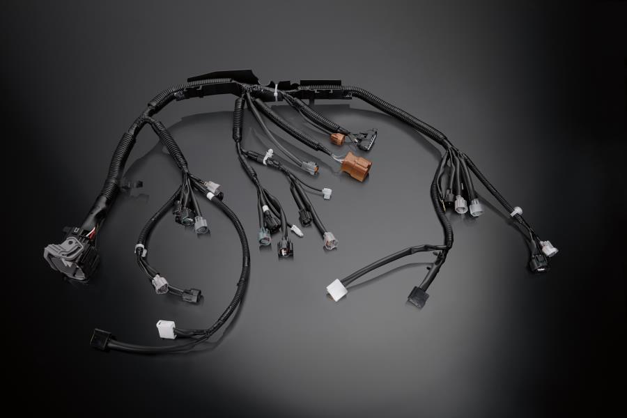
Harness Components
- Connectors: These are the physical interfaces that plug into the ECM and other components. They can range from small, two-pin connectors for individual sensors to large, multi-pin connectors for the ECM itself. Look for markings and color codes on the connectors; these are often noted in the diagram.
- Wires: Obviously, these carry the electrical signals. Key specs include the wire gauge (thickness), which determines the current-carrying capacity, and the wire insulation type (e.g., TXL, GXL), which determines its resistance to heat, chemicals, and abrasion.
- Splices: Points where multiple wires are joined together. These are potential failure points and should be carefully inspected for corrosion or damage.
- Ground Points: Critical connections to the vehicle's chassis, providing a return path for electrical current. Poor grounds can cause all sorts of electrical gremlins.
- Shielding: Some wires, especially those carrying sensitive signals like crankshaft position or camshaft position information, are shielded to prevent electromagnetic interference (EMI).
- Protective Sleeving/Conduit: The harness is typically wrapped in protective sleeving or conduit to protect the wires from physical damage.
Essential Specifications
- Voltage: The ECM typically operates on a 12-volt system, but individual circuits may have different voltage levels. The diagram will often indicate the expected voltage on certain wires.
- Resistance: The resistance of a wire or circuit is a measure of its opposition to the flow of current. High resistance can indicate a corroded connection or damaged wire.
- Continuity: This refers to the presence of a complete, unbroken path for electrical current. A break in continuity means the circuit is open and will not function.
- Current: The flow of electrical charge through a circuit. Knowing the expected current draw of a component can help you identify a short circuit or overload.
Symbols: Decoding the Wiring Diagram
Understanding the symbols used in a wiring diagram is crucial. Here's a breakdown of the common elements:
- Lines: Represent wires. Solid lines indicate a direct connection, while dashed lines may indicate a shielded wire or a connection that is only present under certain conditions.
- Colors: Wires are color-coded for easy identification. For example, a red wire might indicate a power supply, while a black wire might indicate a ground. The diagram will include a color code legend.
- Component Symbols: Each component, such as a sensor, actuator, or relay, is represented by a specific symbol. These symbols are usually standardized, but it's always a good idea to consult the diagram's legend.
- Ground Symbols: Indicate a connection to the vehicle's chassis ground. Different types of ground symbols may indicate different grounding methods.
- Connector Symbols: Show the type and number of pins in each connector. Some diagrams will even show the pin numbers within the connector.
Here are a few examples:
Ground Symbol: Usually looks like an upside-down triangle or a series of parallel lines getting progressively shorter.
Resistor Symbol: A jagged line or a rectangle.
Capacitor Symbol: Two parallel lines, sometimes curved.
How It Works: Signal Flow Through the Harness
The ECM wiring harness acts as the communication highway between the ECM and the engine's various components. Sensors send signals to the ECM, providing information about things like engine temperature, airflow, and throttle position. The ECM processes this information and sends signals to actuators, which control things like fuel injection, ignition timing, and idle speed.
For example, the coolant temperature sensor (CTS) sends a signal to the ECM indicating the engine's coolant temperature. Based on this information, the ECM adjusts the fuel mixture to optimize engine performance. If the CTS signal is incorrect due to a faulty sensor or a wiring problem, the ECM will misinterpret the engine's temperature, leading to poor performance, reduced fuel economy, or even engine damage.
The harness itself is designed to minimize signal loss and interference. Wires are sized appropriately to carry the required current, and shielding is used to protect sensitive signals from EMI. Connectors are designed to provide a reliable and secure connection.
Real-World Use: Basic Troubleshooting Tips
Here are some basic troubleshooting tips using your wiring diagram:
- Visual Inspection: Start by visually inspecting the harness for any signs of damage, such as frayed wires, cracked connectors, or corroded terminals.
- Continuity Testing: Use a multimeter to check the continuity of individual wires. Disconnect the wire from both ends and test for continuity between the two terminals. A lack of continuity indicates a broken wire.
- Voltage Testing: Use a multimeter to check the voltage at various points in the circuit. Compare the measured voltage to the expected voltage indicated on the diagram.
- Resistance Testing: Use a multimeter to check the resistance of components, such as sensors and actuators. Compare the measured resistance to the specifications provided by the manufacturer.
- Pinpoint Shorts: If you suspect a short circuit, use a multimeter to check for continuity between a wire and ground. There should be no continuity between a power wire and ground.
Remember to always disconnect the battery before working on any electrical system to prevent accidental shorts or shocks.
Safety: Handling Sensitive Circuits
Working with the ECM wiring harness can be risky if you're not careful. The most significant risk comes from the potential for electrical shock. Always disconnect the battery before working on the harness, and be careful to avoid touching any exposed wires.
Another risk comes from accidentally damaging the ECM or other components. The ECM is a sensitive electronic device, and it can be easily damaged by static electricity or improper handling. Always use proper grounding techniques when working with electronic components.
Be especially careful when working with the following components:
- Airbag System: Airbags are deployed by an electrical signal, and accidentally triggering an airbag can cause serious injury. Disconnect the airbag system before working on any wiring in the vicinity of the airbags. Consult your vehicle's service manual for proper deactivation procedures.
- High-Voltage Ignition System: The ignition system generates high voltages to fire the spark plugs. Avoid touching any ignition components while the engine is running.
Disclaimer: Always consult your vehicle's service manual and follow proper safety procedures when working on the ECM wiring harness. Improper repairs can damage the ECM or other components, and can even lead to serious injury.
Now that you're armed with this knowledge, you're better equipped to tackle ECM wiring harness issues. Remember to always refer to your vehicle's specific wiring diagram for accurate information. And speaking of diagrams, we have a sample file ready for you to download, so you can see all of these principles in action. Happy wrenching!