Engine Fuel Shut Off Solenoid Wiring Diagram
Alright, let's dive into understanding the fuel shut off solenoid wiring diagram. If you're a DIY mechanic or a car enthusiast tackling fuel system issues, modifying your engine, or even just deepening your understanding of how your engine works, understanding this diagram is critical. It's a vital piece of documentation that can save you time, money, and potential headaches. We'll break down everything you need to know in a clear, approachable way, just like a trusted mechanic would explain it to you.
Purpose: Why This Matters
The fuel shut off solenoid wiring diagram serves several crucial purposes:
- Diagnosis and Repair: When you're experiencing fuel delivery problems, this diagram helps you trace the circuit, identify faulty components (like the solenoid itself, wiring, or the engine control unit (ECU)), and pinpoint the exact cause of the issue.
- Modification and Upgrades: If you're modifying your fuel system, adding aftermarket components, or performing an engine swap, you need to understand how the fuel shut off solenoid integrates with the existing wiring. The diagram provides the roadmap for safe and effective modifications.
- Understanding Engine Operation: Studying the diagram helps you grasp how the fuel system is controlled, how the solenoid interacts with other sensors and actuators, and the role of the ECU in fuel management.
- Preventing Catastrophic Damage: In certain emergency situations or even after an accident, the fuel shut off solenoid can be triggered. Understanding the wiring allows you to manually control the fuel supply if necessary, preventing potential engine flooding or other problems.
Key Specs and Main Parts
Before we get to the diagram itself, let's identify the key components involved:
- Fuel Shut Off Solenoid: This is an electromagnetically controlled valve that, when energized, allows fuel to flow to the engine. When de-energized, it blocks the fuel supply.
- Engine Control Unit (ECU): The "brain" of the engine, the ECU receives input from various sensors and controls the fuel shut off solenoid based on engine conditions, safety parameters, and driver input.
- Ignition Switch: The ignition switch provides the initial power to the system. In many cases, it's the first connection in the fuel shut off solenoid circuit.
- Fuel Pump Relay (Optional): Some systems utilize a fuel pump relay in the solenoid circuit. This relay acts as a switch controlled by the ECU, providing power to the fuel pump and, in some cases, also enabling the fuel shut off solenoid circuit.
- Fuses and Circuit Breakers: These are safety devices designed to protect the circuit from overcurrents. A blown fuse in the fuel shut off solenoid circuit will prevent the solenoid from operating.
- Wiring Harness: The network of wires connecting all the components. These wires have specific gauges (thickness) and insulation to handle the electrical current and environmental conditions.
- Ground Connection: A good, reliable ground connection is crucial for the solenoid to function correctly. A poor ground can cause intermittent problems or complete failure.
Symbols: Deciphering the Code
Understanding the symbols on the wiring diagram is key to interpreting it correctly. Here's a breakdown of common symbols:
- Solid Lines: Represent wires connecting different components. The thickness of the line sometimes indicates the wire gauge (thicker lines = heavier gauge wire).
- Dashed Lines: Often represent shielded cables or wiring that is part of a larger harness but is being highlighted for clarity.
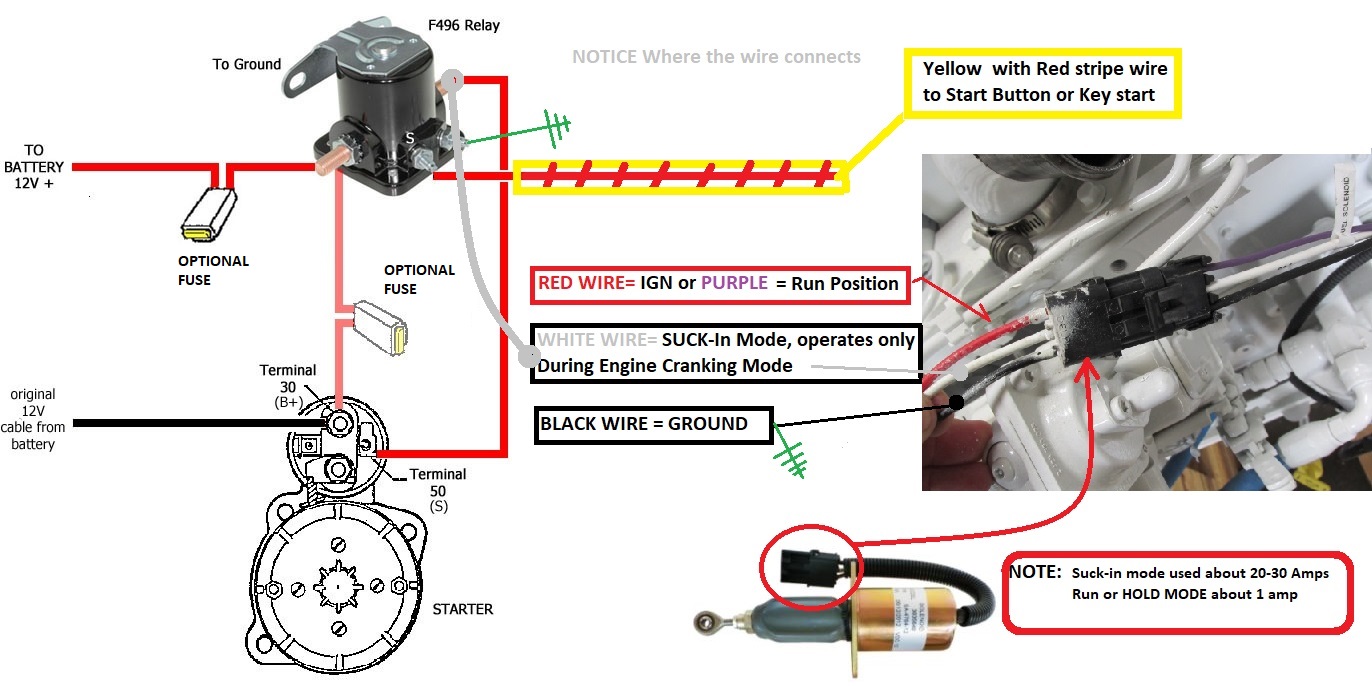
- Colors: Each wire is typically identified by a color code (e.g., Red, Black, Blue/White). This is crucial for identifying the correct wires when troubleshooting. Common color codes are documented in the diagram's legend.
- Symbols for Components:
- Solenoid: Usually represented as a coil with a plunger inside.
- ECU: A rectangular box, often labeled with "ECU" or "PCM" (Powertrain Control Module).
- Fuses: A small zigzag line enclosed in a rectangle.
- Relays: A square with a coil and switch contacts.
- Ground: A downward-pointing series of horizontal lines that get shorter successively, resembling an inverted cone.
- Connectors: Represented as circles or squares with numbers indicating the pin numbers.
- Numbers and Letters: These identify wire gauges, circuit numbers, connector pin numbers, and component identifiers. They provide specific information about each element in the circuit.
How It Works: The Electrical Path
Here's a simplified explanation of how a typical fuel shut off solenoid circuit works:
- When the ignition switch is turned to the "ON" or "RUN" position, power is supplied to the fuel system circuit.
- The ECU monitors various engine sensors, such as the crankshaft position sensor (CKP), camshaft position sensor (CMP), and throttle position sensor (TPS).
- If the ECU determines that the engine should be running (based on sensor inputs and programmed parameters), it sends a signal (usually a ground signal) to the fuel shut off solenoid.
- This signal energizes the solenoid's electromagnet, which pulls the plunger open, allowing fuel to flow through the valve and to the engine.
- If the ECU detects a fault (e.g., an accident, low oil pressure, or an engine overspeed condition), it cuts the signal to the solenoid.
- The solenoid de-energizes, the plunger closes, and fuel flow is stopped, shutting down the engine or preventing it from starting.
Real-World Use: Basic Troubleshooting Tips
Here are some troubleshooting tips using the wiring diagram:
- No Fuel Flow: If the engine won't start and you suspect the fuel shut off solenoid, use a multimeter to check for voltage at the solenoid connector with the ignition on. If there's no voltage, trace the wiring back to the ECU, fuel pump relay, fuse, and ignition switch, checking for breaks, shorts, or blown fuses.
- Intermittent Problems: Intermittent fuel delivery issues can be caused by loose connections, corroded terminals, or a failing solenoid. Use the diagram to identify all the connection points in the circuit and inspect them carefully. A wire wiggling test while monitoring voltage may help.
- Solenoid Won't De-Energize: If the engine won't shut off even with the ignition off, the solenoid might be stuck open or the ECU might be sending a constant signal. Check the ECU signal wire for shorts to ground.
- Check Ground Connections: Ground issues can manifest as a variety of problems. Use the diagram to locate the ground points for the solenoid and ECU, and ensure they are clean and securely connected to the chassis.
- Reading ECU Codes: Use an OBD-II scanner (or equivalent) to read diagnostic trouble codes (DTCs). Many codes will provide clues about problems in the fuel system, pointing you to specific areas to inspect using the wiring diagram.
Safety: Handle with Care
Working with automotive electrical systems can be dangerous. Always disconnect the negative battery cable before working on any electrical components. Fuel systems are particularly risky due to the flammability of gasoline. Never work on the fuel system near open flames or sources of ignition. Be especially careful when working around the ECU and fuel shut off solenoid. Incorrect wiring can damage these components or even cause a fire.
Always double-check your work against the wiring diagram before reconnecting the battery or starting the engine.
Remember, we have a sample fuel shut off solenoid wiring diagram file ready for you to download. This file contains a detailed schematic with component locations and wire color codes that you can use to guide your repairs. Use it alongside this guide, and you'll be well on your way to mastering your engine's fuel system.