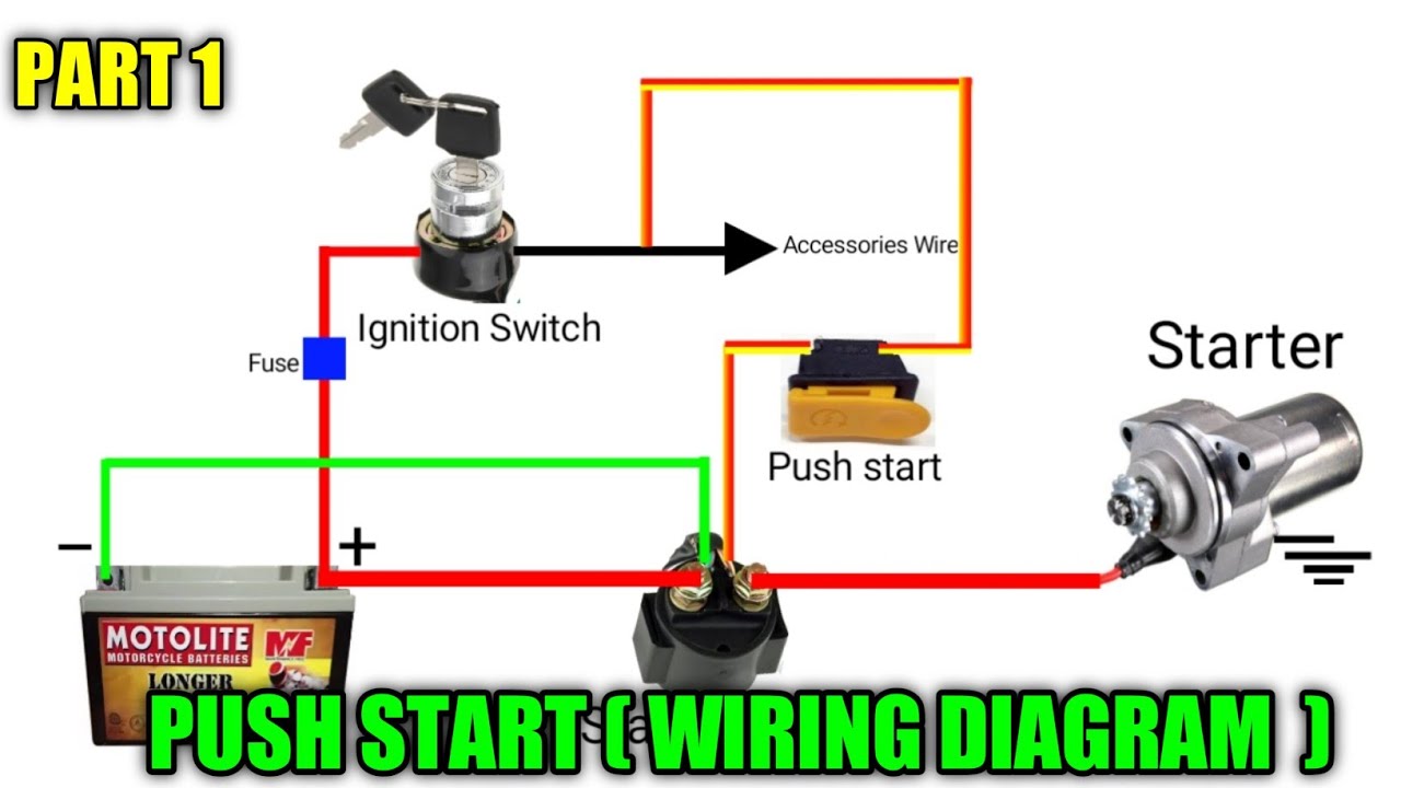
Engine Start Push Button Start Wiring Diagram
Alright, let's dive into the world of push-button start wiring diagrams. Whether you're troubleshooting a no-start issue, adding a remote start system, or just trying to understand the inner workings of your modern vehicle, understanding this diagram is crucial. We're going to break it down in a way that's clear, even if you're not an electrical engineer, but have some experience under the hood.
Purpose of a Push-Button Start Wiring Diagram
Why should you care about this diagram? Simply put, it's your roadmap to the push-button start system. It's essential for:
- Troubleshooting: When your car won't start, the diagram helps you pinpoint the faulty component – whether it's the push-button itself, a relay, a sensor, or a wiring issue.
- Modification: Planning to install a remote start, aftermarket alarm, or other system that interfaces with the ignition? The diagram shows you exactly where to tap into the existing wiring.
- Understanding: Gaining a deeper understanding of your vehicle's electrical system. This knowledge empowers you to perform more complex repairs and modifications.
- Repair: Replacing damaged or worn components like relays or wiring harnesses.
Key Specs and Main Parts
Before we jump into the specifics, let's identify the key components you'll find in a typical push-button start system and their associated specs. Keep in mind that the exact configuration can vary slightly between manufacturers and models.
- Push-Button Start Switch: This is the user interface. It usually operates on a low-voltage signal (typically 12V DC). Its internal circuitry often includes resistance values to signal different operational states (accessory, on, start).
- Ignition Switch (or Module): In push-button systems, the physical ignition switch is often replaced or supplemented by an electronic module. This module interprets the signals from the push-button switch and key fob and then activates the appropriate circuits. It handles high current loads compared to the button.
- Starter Relay: This relay controls the high current flow to the starter motor. It's activated by the ignition module when the start signal is received. Typical coil voltage: 12V DC; contact rating: 30A-50A.
- Accessory Relay: Powers accessories (radio, climate control, etc.) when the ignition is in the accessory or on position. Typical coil voltage: 12V DC; contact rating: 10A-20A.
- Ignition Relay: Powers the ignition system (ECU, fuel pump, ignition coils) when the ignition is in the on position. Typical coil voltage: 12V DC; contact rating: 10A-20A.
- Brake Pedal Position Switch: A safety feature that requires the brake pedal to be depressed before the engine can be started. Typically a simple on/off switch.
- Clutch Pedal Position Switch (manual transmissions): Similar to the brake pedal switch, but for manual transmissions. Prevents starting the engine unless the clutch is engaged. Typically a simple on/off switch.
- Key Fob (Transmitter): Communicates wirelessly with the vehicle's immobilizer system. Transmits an encrypted code to verify the key's legitimacy.
- Immobilizer Module (Receiver): Receives the signal from the key fob and verifies its authenticity. If the key is valid, it allows the engine to start.
- Battery: The source of electrical power for the entire system. Typically 12V DC.
- Ground Connections: Crucial for completing electrical circuits. Poor grounds can cause a variety of problems.
- ECU (Engine Control Unit): The car's computer, receives signals from these various switches, and controls fuel and timing as normal.
Symbols – Lines, Colors, and Icons
Wiring diagrams use standardized symbols and conventions to represent electrical components and connections. Here's a breakdown of the most common:
- Lines: Represent wires. Solid lines usually indicate a direct connection. Dotted lines may represent a shielded wire or a data communication line (e.g., CAN bus).
- Colors: Wires are color-coded to help identify them. Common colors include red (power), black (ground), blue, green, yellow, white, and brown. The exact color code can vary by manufacturer. Always refer to the specific diagram for your vehicle.
- Ground Symbol: Looks like an inverted pyramid or a series of decreasing horizontal lines. Indicates a connection to the vehicle's chassis ground.
- Relay Symbol: Shows a coil (usually a rectangle or circle) and a set of contacts (usually a switch-like symbol).
- Switch Symbol: Represents a switch that can be either open (circuit broken) or closed (circuit completed).
- Fuse Symbol: Looks like a jagged line or a small rectangle. Indicates a fuse, which protects the circuit from overcurrent.
- Connector Symbol: Indicates a point where wires are connected or disconnected.
- Diode Symbol: A triangle pointing to a vertical line. Diodes allow current to flow in only one direction.
Diagrams often include abbreviations to identify components and wiring characteristics. For example, "IGN" might stand for Ignition, "ACC" for Accessory, "GND" for Ground, and "BLK" for Black.
How It Works
The push-button start system operates in several stages:
- Key Fob Authentication: When you enter the vehicle, the immobilizer module communicates with the key fob to verify its identity. If the key is authorized, the immobilizer allows the engine to start.
- Brake/Clutch Pedal Engagement: Pressing the brake pedal (or clutch pedal in a manual transmission) activates the corresponding switch. This signal is a safety interlock that prevents the engine from starting accidentally.
- Push-Button Press: Pressing the push-button start switch sends a low-voltage signal to the ignition module.
- Ignition Module Activation: The ignition module interprets the signal from the push-button switch and the brake/clutch pedal switches. It then activates the accessory relay, ignition relay, and starter relay in sequence.
- Accessory Power: The accessory relay powers up the vehicle's accessories (radio, climate control, etc.).
- Ignition Power: The ignition relay powers up the ignition system (ECU, fuel pump, ignition coils).
- Starter Motor Engagement: The starter relay sends power to the starter motor, which cranks the engine.
- Engine Start: Once the engine starts, the starter motor disengages, and the engine runs on its own power.
The wiring diagram illustrates these steps by showing how the various components are interconnected and how the electrical signals flow through the system. For example, it will show the connection between the brake pedal switch and the ignition module, or the connection between the starter relay and the starter motor.
Real-World Use – Basic Troubleshooting Tips
Let's say your car won't start. Here are a few basic troubleshooting steps you can take, using the wiring diagram as your guide:
- Check the Battery: Use a multimeter to verify that the battery voltage is at least 12V. A dead or weak battery is the most common cause of starting problems.
- Check the Fuses: Consult the wiring diagram and locate the fuses associated with the ignition system and starter motor. Use a multimeter or test light to check for blown fuses.
- Check the Relays: Listen for a clicking sound when you press the push-button start. If you don't hear a click, the relay may be faulty. You can test the relay by swapping it with a known good relay or by using a multimeter to check for continuity across the coil and contacts.
- Check the Brake/Clutch Pedal Switches: Use a multimeter to verify that the brake/clutch pedal switches are working correctly. These switches are usually normally open (NO) and should close when the pedal is depressed.
- Check the Push-Button Switch: Use a multimeter to verify that the push-button switch is sending a signal to the ignition module when pressed.
- Check Grounds: Inspect ground connections, especially those connected to the engine block and chassis. Clean and tighten any corroded or loose ground connections. This is a common problem area.
If you're comfortable working with electrical circuits, you can use the wiring diagram to trace the circuit and identify any breaks or shorts. Remember to always disconnect the battery before working on the electrical system.
Safety – Highlight Risky Components
Working with automotive electrical systems can be dangerous if you're not careful. Here are a few safety precautions to keep in mind:
- Disconnect the Battery: Always disconnect the negative battery cable before working on the electrical system. This will prevent accidental shorts and electrical shocks.
- Work in a Well-Ventilated Area: Batteries can produce explosive gases. Work in a well-ventilated area and avoid sparks or open flames.
- Use Proper Tools: Use insulated tools designed for automotive electrical work.
- Be Careful Around Airbags: Airbags are triggered by electrical signals. Consult the vehicle's service manual for instructions on how to disable the airbag system before working near airbags.
- High Current Circuits: Be extremely careful when working around high-current circuits, such as the starter motor circuit. These circuits can deliver a powerful shock.
- ECU Sensitivity: Avoid static electricity around the ECU. Use an antistatic wrist strap when handling or working near it.
Always consult a qualified mechanic if you're not comfortable working on the electrical system yourself. Trying to fix things without understanding the wiring diagram can be *very* dangerous and could result in damage to your vehicle or injury to yourself.
We have a standard push-button start wiring diagram available for download. Remember, this is a *general* diagram. You'll need to find the specific diagram for *your* vehicle's make, model, and year to ensure accuracy. Understanding this general diagram gives you a great foundation for interpreting any diagram you come across. Good luck!