
Engine Throttle Position Sensor Diagram
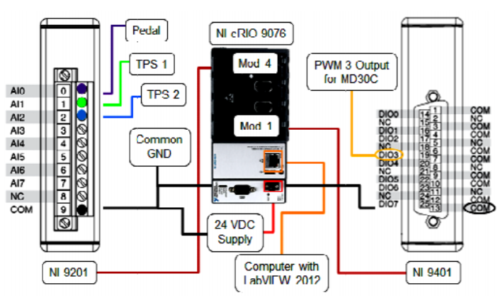
So, you're diving into the workings of your engine's throttle position sensor (TPS)? Good choice. Understanding this little component is crucial for smooth running, good fuel economy, and accurate diagnostics. This article breaks down the TPS wiring diagram, giving you the knowledge to troubleshoot issues, perform repairs, or even plan modifications with confidence.
Purpose – Why the TPS Wiring Diagram Matters
A TPS wiring diagram is essentially a roadmap of the sensor's electrical connections. Why is this important? Because:
- Troubleshooting: When you're experiencing idle problems, hesitation on acceleration, or even a check engine light related to the throttle system, the diagram helps you pinpoint wiring faults like shorts, opens, or poor connections.
- Repair: If you need to replace the TPS connector, repair damaged wiring, or perform a wiring harness repair, you need to know where each wire goes. The diagram provides this crucial information.
- Modification: Planning to install an aftermarket throttle body or a programmable ECU? The diagram will help you understand how the TPS signal interacts with the engine management system.
- Learning: Simply understanding how the TPS integrates into the overall engine control system provides a deeper understanding of automotive electronics.
In short, the diagram is your guide to understanding, diagnosing, and repairing anything related to the TPS and its electrical connections.
Key Specs and Main Parts of a TPS Circuit
Before we dive into the diagram itself, let's cover the essential components of the TPS circuit:
- Throttle Position Sensor (TPS): This is the star of the show. Typically, it's a potentiometer (a variable resistor) that outputs a voltage signal proportional to the throttle plate's angle. The ECU (Engine Control Unit) uses this signal to determine the engine's load and adjust fueling, ignition timing, and other parameters.
- Connector: This is how the TPS connects to the wiring harness. TPS connectors usually have three wires: a 5-volt reference signal from the ECU, a ground connection, and the signal wire carrying the voltage reading back to the ECU.
- Wiring Harness: The network of wires that connects the TPS to the ECU and other components. These wires are typically color-coded to aid in identification.
- ECU (Engine Control Unit): The brain of the operation. The ECU receives the TPS signal, processes it along with inputs from other sensors, and controls the engine's operation.
- Throttle Body: The component that houses the throttle plate, which regulates airflow into the engine. The TPS is usually mounted directly on the throttle body.
Key Specs:
- Voltage Range: The TPS typically outputs a voltage range from around 0.5 volts at closed throttle to around 4.5 volts at wide-open throttle (WOT). This range can vary slightly depending on the vehicle.
- Resistance Range: If you're testing the TPS using an ohmmeter, the resistance should change smoothly and linearly as the throttle plate is moved. Look for any sudden jumps or discontinuities in the resistance reading, which could indicate a faulty TPS.
- Operating Temperature: TPSs are designed to operate within a specific temperature range. Extreme temperatures can affect their accuracy and reliability.
Understanding the Symbols in a TPS Wiring Diagram
Wiring diagrams use standardized symbols to represent electrical components and connections. Here's a breakdown of the common symbols you'll encounter in a TPS diagram:
- Solid Lines: Represent wires. The thickness of the line doesn't usually indicate wire gauge in automotive diagrams.
- Dashed Lines: Can indicate shielded wiring, ground connections, or internal connections within a component.
- Circles or Ovals: Represent connectors or terminal points where wires connect. Numbers or letters inside the circle or oval indicate the pin number or terminal designation.
- Rectangles: Usually represent components like sensors, relays, or control modules.
- Ground Symbol: Looks like a downward-pointing arrow with horizontal lines. Indicates a connection to the vehicle's chassis ground.
- Color Codes: Wires are typically identified by color codes, such as "BLU" for blue, "GRN" for green, "RED" for red, and "BLK" for black. These codes are usually abbreviated.
Important: Always refer to the specific wiring diagram for your vehicle, as symbols and conventions can vary slightly between manufacturers.
How the TPS Circuit Works
The TPS circuit works on a simple principle: as the throttle plate opens, the TPS rotates, changing the resistance of the potentiometer. This change in resistance alters the voltage signal sent to the ECU.
Here's a step-by-step breakdown:
- The ECU sends a stable 5-volt reference signal to the TPS. This is like providing the power supply for the sensor.
- The TPS, acting as a variable resistor, uses the position of the throttle plate to divide the 5-volt signal.
- The resulting voltage signal, which varies between approximately 0.5 volts and 4.5 volts, is sent back to the ECU.
- The ECU interprets this voltage signal as the throttle position. The closer the voltage is to 4.5 volts, the wider the throttle is open.
- The ECU uses the throttle position information, along with data from other sensors like the mass airflow sensor (MAF) and engine coolant temperature sensor (ECT), to determine the correct amount of fuel to inject, the ignition timing, and other engine parameters.
Analogy: Think of the TPS like a dimmer switch on a light. As you turn the dimmer switch, the resistance changes, which in turn changes the voltage applied to the lightbulb, making it brighter or dimmer. The TPS works in a similar way, providing a variable voltage signal to the ECU based on the throttle plate's position.
Real-World Use – Basic Troubleshooting Tips
Here are a few basic troubleshooting tips when dealing with TPS-related issues, utilizing the wiring diagram:
- Check for Voltage at the TPS Connector: Use a multimeter to verify that the TPS is receiving the 5-volt reference signal from the ECU. If the voltage is missing, there may be a problem with the ECU or the wiring harness.
- Test the TPS Signal Wire: With the ignition on and the engine off, use a multimeter to measure the voltage on the TPS signal wire. As you slowly open the throttle, the voltage should increase smoothly and linearly. Look for any dead spots or erratic voltage changes.
- Inspect the Wiring Harness: Visually inspect the wiring harness for any signs of damage, such as frayed wires, corroded connectors, or loose connections. Pay close attention to the wiring near the TPS connector, as this area is often exposed to heat and vibration.
- Check for Continuity: Use a multimeter to check the continuity of the wires between the TPS connector and the ECU. This will help you identify any open circuits.
- Scan for Diagnostic Trouble Codes (DTCs): Use an OBD-II scanner to check for any DTCs related to the TPS. These codes can provide valuable clues about the nature of the problem. Common codes include P0120 (Throttle Position Sensor/Switch A Circuit Malfunction) and P0121 (Throttle Position Sensor/Switch A Circuit Range/Performance Problem).
Safety – Highlight Risky Components
Working on automotive electrical systems involves certain risks. Here are a few safety precautions to keep in mind:
- Disconnect the Battery: Before working on any electrical components, disconnect the negative battery cable to prevent electrical shocks or short circuits.
- Avoid Piercing Wires: Avoid piercing wires with test probes, as this can damage the insulation and lead to corrosion. Instead, use back-probing techniques or connector breakout boxes.
- Use Proper Tools: Use high-quality electrical testing tools, such as a multimeter with sharp probes and insulated handles.
- Be Aware of High-Voltage Circuits: While the TPS circuit itself is low voltage, be aware of other high-voltage circuits in the engine compartment, such as the ignition system.
- Work in a Well-Ventilated Area: When working with solvents or cleaners, work in a well-ventilated area to avoid inhaling harmful fumes.
- Be Careful Around Moving Parts: Keep your hands and tools away from moving parts, such as the throttle linkage, when the engine is running.
The TPS circuit itself doesn't present a high-voltage risk; however, always exercise caution when working near any electrical components on your vehicle. Follow safety procedures to protect yourself from injury.
We have a detailed TPS wiring diagram readily available for download. This comprehensive diagram will provide you with a clear and accurate visual representation of the TPS circuit, making troubleshooting and repairs easier than ever. Take your automotive knowledge and DIY skills to the next level – the diagram is just a click away!