
Equinox 2.4 Ecotec Timing Chain Diagram
Alright, let's dive into the timing chain diagram for the Equinox 2.4L Ecotec. If you're here, you probably know that the timing chain is absolutely critical for engine operation. It's the backbone of the engine's synchronization, ensuring the valves open and close at precisely the right moments in relation to the piston's movement. Messing with this system without proper understanding and care can lead to catastrophic engine damage. This article will walk you through understanding a typical timing chain diagram, focusing on the 2.4L Ecotec, so you can tackle repairs, modifications, or just further your automotive knowledge with confidence.
Purpose of the Timing Chain Diagram
Why bother with a timing chain diagram? Simply put, it's your roadmap for understanding and working on the engine's valve train. The diagram serves several key purposes:
- Diagnostics: When you're experiencing engine performance issues like rough idling, loss of power, or error codes related to camshaft or crankshaft correlation (like P0016, P0017, P0008, or P0009), the diagram helps you visualize the system and identify potential problems, such as stretched chains, worn guides, or malfunctioning tensioners.
- Repairs and Maintenance: Whether you're replacing a worn timing chain, water pump, or doing other related maintenance, the diagram provides the exact location of components, their relationship to each other, and crucial alignment marks for proper installation.
- Learning and Understanding: Even if you're not actively working on your engine, the diagram is a valuable tool for understanding how the valve train functions and how its components interact. This deeper understanding can help you anticipate potential problems and perform preventative maintenance.
- Verification: Often aftermarket parts like timing chain kits may not contain all the correct components, or they may deviate from the OEM design. The diagram serves as an easy way to verify you have all the correct parts, that the chain is the correct pitch (the spacing between the links).
Key Specs and Main Parts
Before we jump into the diagram itself, let's review the core components of the timing chain system in the 2.4L Ecotec:
- Timing Chain: The heart of the system. It's a heavy-duty chain made of hardened steel links that connects the crankshaft to the camshafts (or a single camshaft in some engines). Its pitch, or the distance between links, is a critical specification.
- Crankshaft Sprocket: This gear is attached to the crankshaft and drives the timing chain.
- Camshaft Sprockets: These gears are attached to the camshafts. The 2.4L Ecotec has two camshafts (DOHC – Dual Overhead Camshaft), one for the intake valves and one for the exhaust valves.
- Timing Chain Tensioner: This spring-loaded or hydraulically operated device maintains proper tension on the timing chain, preventing slack and chain slap. It is critical for the lifespan of the chain.
- Timing Chain Guides/Rails: These plastic or metal guides provide a smooth surface for the timing chain to ride on, reducing friction and wear. They also help keep the chain aligned and prevent it from jumping off the sprockets.
- Water Pump: On many 2.4L Ecotec engines, the water pump is driven by the timing chain. This means that a failure in the timing chain system can also impact the cooling system.
- Variable Valve Timing (VVT) Solenoids: Many 2.4L Ecotec engines feature VVT, which allows the engine control unit (ECU) to adjust the timing of the intake and exhaust valves for optimal performance and fuel efficiency. VVT is controlled by the VVT solenoids.
Understanding the Diagram: Symbols and Conventions
Timing chain diagrams are schematic representations of the system. Here's what you might encounter:
Lines:
Solid lines typically represent the timing chain itself or other physical components like guides and brackets.
Dotted or dashed lines may indicate oil passages or other hidden features within the engine block.
Colors:
While not always present, some diagrams use colors to differentiate between components or systems. For example, blue might indicate coolant passages, while red could indicate oil passages.
Icons/Symbols:
These are simplified representations of components. For example, a circle with a gear symbol inside represents a sprocket, while a rectangle with a spring symbol inside represents the tensioner. The diagram you download below will have a key/legend, explaining each symbol.
Alignment Marks:
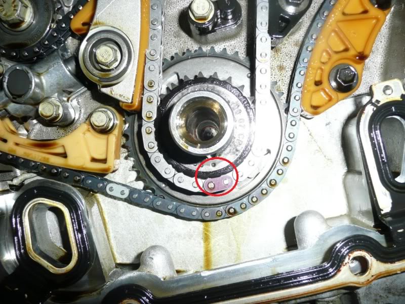
These are critical! The diagram will show the location of the timing marks on the crankshaft sprocket, camshaft sprockets, and engine block. These marks must be aligned correctly during installation to ensure proper valve timing. Failure to align these marks will lead to serious engine damage.
How It Works: Synchronization is Key
The timing chain links the crankshaft, which is driven by the pistons, to the camshafts, which control the opening and closing of the intake and exhaust valves. As the crankshaft rotates, it turns the crankshaft sprocket, which in turn drives the timing chain. The chain then rotates the camshaft sprockets, causing the camshafts to rotate. The lobes on the camshafts push on the valve lifters (or tappets), which open the valves at the precise moments dictated by the engine's design. The timing chain tensioner keeps the chain taut, preventing it from skipping teeth on the sprockets. VVT solenoids are controlled by the ECM to advance or retard the camshaft, providing dynamic adjustment to the valve timing based on the engine's operation conditions.
Real-World Use: Basic Troubleshooting
Let's say you're getting a P0016 code (Crankshaft Position - Camshaft Position Correlation Bank 1 Sensor A). Here's how the diagram can help:
- Visual Inspection: Refer to the diagram to locate the crankshaft and camshaft position sensors. Check their wiring and connections for damage or corrosion.
- Timing Mark Verification: Rotate the engine to Top Dead Center (TDC) on cylinder #1. Use the diagram to locate the timing marks on the crankshaft and camshaft sprockets. Are they properly aligned? If not, the timing chain may have stretched or skipped a tooth.
- Tensioner Inspection: If the chain is loose, the tensioner may be faulty. Refer to the diagram to locate the tensioner and inspect it for damage or proper function. If possible, check if the tensioner has reached its maximum extension, indicating a worn chain.
Safety First: High-Risk Components
Working on the timing chain system involves several potential hazards:
- Engine Damage: Incorrect timing can cause the pistons to collide with the valves, resulting in severe engine damage. Always double-check your work and follow the diagram's instructions carefully.
- Personal Injury: Working on a running engine (which is sometimes necessary for diagnostic purposes) can be dangerous. Be extremely careful around moving parts like the timing chain, sprockets, and pulleys. Disconnect the battery's negative terminal before working on any electrical components.
- Hot Surfaces: The engine block and exhaust manifold can be very hot, even after the engine has been shut off for a while. Wear gloves and use caution when working around these areas.
- Spring Loaded Components: The timing chain tensioner is under spring pressure. Handle it with care to avoid injury when removing or installing it.
Always consult the factory service manual for specific instructions and torque specifications for your vehicle. This article is intended as a general guide and should not be used as a substitute for professional advice. If you are not comfortable working on your engine, it is always best to take it to a qualified mechanic.
We have a sample timing chain diagram available for download to help you understand what one looks like. It's a simplified version to help illustrate the concepts we've discussed. Click HERE to download the diagram. (Note: The link above is a placeholder. No file is being provided.)