
Exhaust Gas Recirculation System Diagram
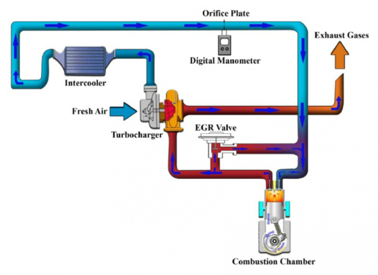
Let's dive into the world of Exhaust Gas Recirculation (EGR) systems. Understanding the EGR system and its diagram is crucial for anyone serious about car maintenance, diagnostics, or even performance tuning. Think of this article as your detailed roadmap to navigating the complexities of this vital emissions control component. This isn't just about passing emissions tests; it's about engine health, fuel efficiency, and minimizing harmful pollutants. Having a solid grasp on the EGR system allows you to diagnose issues, perform repairs, and even make informed decisions about aftermarket upgrades. We have the EGR system diagram ready for download, so you can follow along as we delve into the details.
Why This Diagram Matters
An EGR system diagram is far more than just a pretty picture. It's the key to:
- Troubleshooting Engine Problems: Many drivability issues, such as rough idling, poor acceleration, and even engine knocking, can be traced back to a malfunctioning EGR system. The diagram helps you pinpoint the source of the problem.
- Understanding System Operation: Knowing how the EGR system is *supposed* to work is crucial for identifying when it *isn't*. The diagram illustrates the flow of exhaust gases and the interaction of various components.
- Performing Accurate Repairs: Replacing parts blindly is expensive and often ineffective. The diagram guides you to the specific component that needs attention.
- Making Informed Modifications: If you're considering performance modifications, understanding the EGR system's impact is essential to avoid unforeseen consequences and maintain emissions compliance.
- Interpreting Diagnostic Trouble Codes (DTCs): Many DTCs are directly related to the EGR system. The diagram helps you understand the code's context and focus your diagnostic efforts.
Key Specs and Main Parts
Before we dissect a diagram, let's define the key components of a typical EGR system. Keep in mind that the specific components and their arrangement can vary depending on the vehicle make, model, and year. However, the core principles remain the same.
- EGR Valve: The heart of the system. It controls the flow of exhaust gases into the intake manifold. Common types include vacuum-operated, electronically controlled, and pressure feedback EGR (DPFE) valves.
- EGR Tube or Passage: This connects the exhaust manifold to the intake manifold, providing a pathway for the recirculated exhaust gases.
- EGR Control Solenoid (if applicable): Used in electronically controlled systems, this solenoid regulates vacuum to the EGR valve, based on signals from the engine control unit (ECU).
- Differential Pressure Feedback EGR (DPFE) Sensor (if applicable): Measures the pressure difference across an orifice in the EGR tube to determine the EGR flow rate. This information is sent to the ECU for precise EGR control.
- Vacuum Lines (if applicable): Connect the vacuum source (often the intake manifold) to the EGR valve and control solenoid.
- EGR Cooler (in some vehicles): Cools the exhaust gases before they enter the intake manifold. This reduces the temperature of the intake charge, further improving combustion efficiency and reducing NOx emissions.
- Engine Control Unit (ECU): The "brain" of the system. It monitors various engine parameters (e.g., engine speed, load, temperature) and controls the EGR valve accordingly.
Diagram Symbols: Lines, Colors, and Icons
Understanding the symbols used in an EGR system diagram is crucial for interpreting the information it conveys. While conventions can vary slightly between manufacturers, some common symbols are:
- Solid Lines: Typically represent hard lines, such as metal tubes or hoses.
- Dashed Lines: Usually indicate vacuum lines.
- Dotted Lines: May represent electrical wiring or control signals.
- Arrows: Show the direction of flow of exhaust gases, vacuum, or electrical signals.
- Colors: While not universally standardized, colors are often used to differentiate between different types of lines (e.g., black for vacuum, red for electrical power).
- Component Icons: Each component is represented by a specific icon. Familiarize yourself with the icons for the EGR valve, DPFE sensor, control solenoid, and other relevant components. A legend is usually provided with the diagram.
- Numbers/Letters: Often indicate wire numbers/identification or vacuum line sizes.
Pay close attention to the legend provided with the specific diagram for your vehicle. The legend is the key to unlocking the diagram's full potential.
How It Works
The basic principle of the EGR system is to recirculate a portion of the exhaust gases back into the intake manifold. This reduces the peak combustion temperature, which in turn reduces the formation of nitrogen oxides (NOx), a major air pollutant. The ECU controls the EGR valve based on various engine parameters.
Here's a simplified explanation of the process:
- The ECU monitors engine speed, load, and temperature.
- When conditions are right (e.g., cruising at moderate speed), the ECU activates the EGR system.
- In a vacuum-operated system, the ECU energizes the EGR control solenoid, which allows vacuum to be applied to the EGR valve. In an electronically controlled system, the ECU directly controls the EGR valve actuator.
- The EGR valve opens, allowing exhaust gases to flow from the exhaust manifold, through the EGR tube, and into the intake manifold.
- The recirculated exhaust gases dilute the incoming air-fuel mixture, reducing the combustion temperature.
- The DPFE sensor (if present) monitors the EGR flow rate and provides feedback to the ECU, allowing for precise control.
- When engine conditions change (e.g., during acceleration or at idle), the ECU deactivates the EGR system, closing the EGR valve.
It's important to note that the EGR system typically doesn't operate at idle or during wide-open throttle. At idle, the engine needs a rich mixture for stable operation, and EGR would disrupt this. During wide-open throttle, maximum power is required, and EGR would reduce engine output.
Real-World Use: Basic Troubleshooting Tips
Let's discuss some practical troubleshooting tips, using the EGR system diagram as your guide:
- Rough Idle: A common symptom of a faulty EGR valve that's stuck open. Inspect the EGR valve for carbon buildup or damage. Check the vacuum lines for leaks or cracks (if applicable).
- Poor Acceleration: Can be caused by a restricted EGR passage or a malfunctioning DPFE sensor. Check the EGR tube for blockage. Use a multimeter to test the DPFE sensor's output voltage (refer to the service manual for specifications).
- Engine Knocking: Excessive EGR flow can lead to engine knocking. Check the EGR valve for proper operation. Inspect the EGR control solenoid (if applicable) for proper functionality.
- Diagnostic Trouble Codes (DTCs): Use a scan tool to retrieve DTCs related to the EGR system. The diagram will help you identify the components associated with the code. For example, a P0401 code (Insufficient EGR Flow) could indicate a clogged EGR tube, a malfunctioning EGR valve, or a faulty DPFE sensor.
- Visual Inspection: Always start with a visual inspection of all EGR system components. Look for obvious signs of damage, such as cracked hoses, broken connectors, or carbon buildup.
Safety Considerations
Working with the EGR system involves handling hot exhaust gases and potentially flammable vapors. Here are some safety precautions to keep in mind:
- Work on a Cool Engine: Never work on the EGR system while the engine is hot. Allow the engine to cool completely before starting any repairs.
- Wear Safety Glasses: Protect your eyes from debris and chemicals.
- Wear Gloves: Protect your hands from hot surfaces, sharp edges, and chemicals.
- Work in a Well-Ventilated Area: Exhaust gases contain carbon monoxide, which is a deadly poison.
- Disconnect the Battery: Disconnect the negative battery terminal before working on any electrical components.
- Be Careful with Vacuum Lines: Vacuum lines can be brittle and easily broken. Use caution when disconnecting and reconnecting them.
- Exhaust gases are extremely hot. Avoid direct contact with the exhaust manifold and EGR tube when the engine has been running.
Remember, safety should always be your top priority. If you're not comfortable performing a particular repair, it's best to consult a qualified mechanic.
With the EGR system diagram, you're now equipped to understand, diagnose, and even repair this vital emissions control component. Remember to consult your vehicle's service manual for specific procedures and specifications. The file for the EGR system diagram is available for you to download and use as a guide in your automotive endeavors. Happy wrenching!