External Regulator Alternator Wiring Diagram
So, you're looking to tackle an external regulator alternator wiring diagram, eh? Good on you. This is a topic that can seem daunting at first, but with a solid understanding of the basics, you can diagnose issues, perform upgrades, or even build a custom electrical system. This guide is geared towards the experienced DIYer who's comfortable with basic automotive electrical work but wants to delve deeper into the specifics of external regulator alternator systems.
Why Bother Understanding External Regulator Alternator Wiring?
Why even bother with this ancient technology? Well, several reasons. Firstly, you might be working on a classic car that came equipped with one. Understanding the original wiring is crucial for restoration or modification. Secondly, even on newer vehicles, knowing the fundamentals of how an alternator charges a battery is incredibly valuable for troubleshooting charging system problems. And finally, you might be retrofitting an older engine into a newer chassis or building a custom hot rod where an external regulator setup might be preferred due to its simplicity and robustness.
Whether you're troubleshooting a malfunctioning classic car, planning a performance upgrade, or simply expanding your automotive electrical knowledge, grasping the intricacies of an external regulator alternator wiring diagram is a skill that will serve you well. It allows you to diagnose charging problems accurately, perform safe and effective repairs, and even customize your vehicle's electrical system.
Key Specifications and Main Parts
Before diving into the wiring diagram itself, let's identify the core components and their roles. The external regulator alternator system, while simpler than modern internally regulated systems, still relies on precise interplay between its parts.
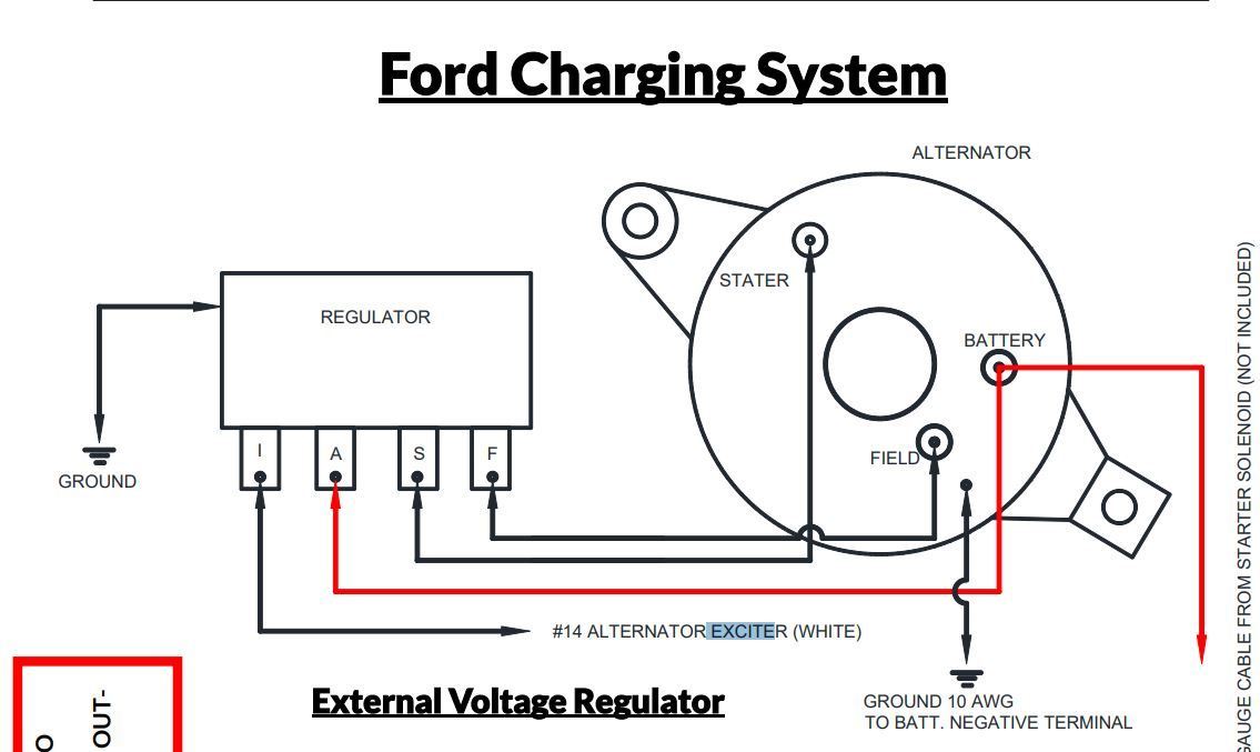
- Alternator: This is the heart of the system. It converts mechanical energy (engine rotation) into electrical energy (charging the battery and powering the vehicle's electrical loads). Common types include Delco Remy and Ford alternators. Look for specs like output amperage (e.g., 63 amp, 100 amp) and pulley type.
- External Voltage Regulator: This crucial component controls the alternator's output voltage. It senses the battery voltage and adjusts the field current supplied to the alternator, thereby regulating the charging voltage. Common types include mechanical (vibrating contact) and solid-state regulators.
- Battery: The battery stores electrical energy and provides power when the alternator is not producing enough.
- Ignition Switch: Provides power to the voltage regulator and other circuits when the engine is running.
- Wiring Harness: The network of wires connecting all the components.
- Ammeter or Voltmeter: A gauge that displays the charging system's performance. An ammeter shows the current flow (charge or discharge), while a voltmeter shows the voltage level.
- Fusible Link or Fuse: A safety device that protects the circuit from overcurrent.
Decoding the Wiring Diagram: Symbols, Lines, and Colors
Understanding the symbols used in a wiring diagram is essential for interpreting the information it presents. Here's a breakdown of common symbols and conventions:
- Solid Lines: Represent wires. The thickness of the line *sometimes* indicates wire gauge (thicker = larger gauge).
- Dashed Lines: May represent ground connections or shielded wiring.
- Circles: Often represent connections or terminals.
- Rectangles: Typically represent components like the voltage regulator or ignition switch.
- Resistors: Zigzag line.
- Capacitors: Two parallel lines.
- Ground Symbol: Usually looks like a downward-pointing triangle or a series of lines decreasing in length. Indicates a connection to the vehicle's chassis (ground).
Wire colors are standardized to some extent, but can vary between manufacturers and even model years. Here are some common color codes:
- Red: Battery power (usually unfused).
- Orange/Yellow: Switched power (from the ignition switch).
- Black: Ground.
- Blue/Green: Often used for field wires or indicator lights.
Always refer to the specific wiring diagram for your vehicle or application, as color codes can differ.
How It Works: A Step-by-Step Explanation
Here's a simplified explanation of how an external regulator alternator system works:
- Ignition On: When the ignition switch is turned on, power is supplied to the voltage regulator, typically through a resistor or resistance wire (to limit current).
- Voltage Regulator Senses Battery Voltage: The regulator monitors the battery voltage.
- Field Current Control: Based on the battery voltage, the regulator adjusts the amount of current flowing through the field winding of the alternator. A low battery voltage will cause the regulator to increase the field current, while a high voltage will cause it to decrease the field current.
- Alternator Output: The amount of current flowing through the field winding directly affects the alternator's output voltage. More field current = higher output voltage.
- Charging the Battery: The alternator's output voltage is higher than the battery voltage, allowing current to flow into the battery, charging it.
- Voltage Regulation: The regulator continuously adjusts the field current to maintain a stable charging voltage (typically around 13.8-14.5 volts).
The key to understanding this system is realizing that the voltage regulator is constantly monitoring and adjusting the alternator's output to keep the battery properly charged without overcharging it.
Real-World Use: Basic Troubleshooting Tips
Here are some common problems you might encounter with an external regulator alternator system and how to troubleshoot them:
- Battery Not Charging:
- Check the belt tension. A slipping belt won't allow the alternator to spin fast enough.
- Check the battery connections. Clean and tighten them.
- Check the fusible link or fuse protecting the charging circuit.
- Check the voltage regulator connections. Make sure they are clean and secure.
- Test the alternator output. Use a voltmeter to measure the voltage at the alternator's output terminal. It should be above battery voltage when the engine is running.
- Test the voltage regulator. Use a multimeter to check the voltage at the regulator's terminals and compare them to the specifications in the service manual.
- Overcharging:
- This is usually a sign of a faulty voltage regulator. Replace the regulator.
- Check the ground connections for the regulator and alternator. A poor ground can cause voltage regulation problems.
- Indicator Light Stays On:
- Could indicate a problem with the alternator, voltage regulator, or wiring.
- Check the voltage at the alternator's output terminal. If it's low, the alternator may be faulty.
Remember to always disconnect the battery's negative terminal before working on the electrical system.
Safety First: Risky Components and Precautions
Working with automotive electrical systems involves inherent risks. Here are some key safety precautions to keep in mind:
- Battery: Batteries contain sulfuric acid, which is highly corrosive. Wear eye protection and gloves when handling batteries.
- High Voltage: While the charging system operates at relatively low voltage (12-14 volts), short circuits can generate significant heat and sparks. Always disconnect the battery before working on the electrical system.
- Explosive Gases: Batteries can produce explosive hydrogen gas. Keep sparks and flames away from batteries.
- Fusible Links/Fuses: Never bypass a fusible link or fuse. They are there to protect the circuit from overcurrent and prevent fires.
Always consult the vehicle's service manual for specific safety precautions and wiring diagrams.
Important: Before working on any electrical system, disconnect the negative battery cable. This will prevent accidental shorts and potential damage to the vehicle's electrical components.
By understanding the principles outlined above and following proper safety precautions, you can confidently tackle external regulator alternator wiring diagrams and troubleshoot related issues.
We have a detailed wiring diagram file available for download to help with your specific project. It provides a comprehensive visual representation of the system, making diagnosis and repair much easier.