F150 4x4 Vacuum Hose 5.4 Triton Vacuum Diagram
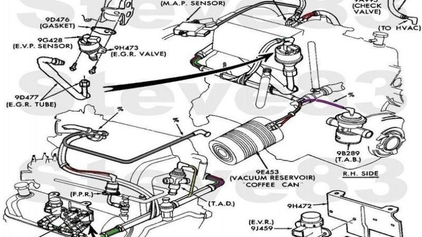
Alright, let's dive into the vacuum system diagram for your F-150 4x4 with the 5.4L Triton engine. This intricate network of hoses and valves is often overlooked, but it plays a crucial role in everything from your 4-wheel drive engagement to your HVAC system. Understanding this system isn't just about fixing problems; it's about gaining a deeper understanding of your truck and being able to diagnose issues effectively.
Purpose of Understanding the Vacuum Diagram
Why bother understanding this diagram? Well, for starters, vacuum leaks are notorious for causing a range of issues. They can lead to:
- Rough idling: The engine control unit (ECU) struggles to maintain the correct air-fuel mixture.
- Poor fuel economy: Excess air entering the engine leans out the mixture, requiring more fuel.
- HVAC problems: Mode doors might not switch correctly (e.g., air stuck on defrost).
- 4x4 engagement issues: The 4-wheel drive system relies on vacuum to engage and disengage the front axle.
- Check engine light (CEL): The ECU detects lean conditions or other vacuum-related faults and throws a code.
Having the vacuum diagram allows you to systematically trace hoses, identify components, and pinpoint the source of leaks. It's also invaluable for restoring modified vacuum systems back to their original configuration, performing accurate repairs, and even gaining a better understanding of how various engine components work together.
Key Specs and Main Parts of the 5.4L Triton Vacuum System
The 5.4L Triton vacuum system, like most vacuum systems, relies on manifold vacuum. This is the vacuum created in the intake manifold when the engine is running. Let’s look at the key components:
Vacuum Source:
The primary vacuum source is the intake manifold. A vacuum port on the manifold connects to the main vacuum line, which then branches out to supply vacuum to various components.
Vacuum Reservoir:
The vacuum reservoir is a storage tank that maintains a consistent vacuum supply, especially during periods of low engine vacuum (e.g., during acceleration). It's usually a black, spherical or cylindrical container, often located in the engine compartment or fender well. It ensures consistent vacuum to components such as the HVAC mode doors.
Vacuum Check Valves:
Check valves are one-way valves that prevent vacuum from bleeding off when the engine is under load. These are crucial for maintaining vacuum in the reservoir and other critical circuits. They ensure vacuum is only applied in one direction, preventing backflow.
Vacuum Actuators:
These devices convert vacuum pressure into mechanical motion. Examples include:
- HVAC door actuators: Control airflow direction within the cabin.
- 4x4 IWE (Integrated Wheel End) actuators: Engage and disengage the front axle.
- EGR (Exhaust Gas Recirculation) valve actuator: Opens and closes the EGR valve, reducing emissions.
Vacuum Control Solenoids:
These are electrically controlled valves that regulate the flow of vacuum to various actuators. The ECU controls these solenoids based on engine parameters. For example, the IWE solenoid controls vacuum to the front axle actuators.
Vacuum Hoses:
Of course, the entire system relies on a network of vacuum hoses. These come in various sizes and materials and connect all the components. Identifying the correct hose routing is paramount. Look for brittle, cracked, or disconnected hoses, as these are common sources of leaks.
Understanding the Symbols in the Vacuum Diagram
Vacuum diagrams use standardized symbols to represent components and connections. Here's a breakdown of some common symbols:
- Solid lines: Typically represent vacuum hoses. Different thicknesses might indicate hose diameter.
- Dashed lines: May indicate control wires for solenoids or other electrical components.
- Circles or ovals: Often represent vacuum reservoirs or actuators.
- Squares or rectangles: Can represent vacuum solenoids or control modules.
- Arrows within lines: Indicate the direction of vacuum flow. Important for understanding check valve orientation.
- Color Coding (if present): Sometimes, diagrams use color coding to distinguish different vacuum circuits. For example, the 4x4 engagement system might be highlighted in a specific color.
Pay close attention to the notes and labels on the diagram. These often provide crucial information about specific components or connections.
How the 5.4L Triton Vacuum System Works
Let's break down how the vacuum system powers a couple of key functions:
4x4 Engagement:
When you select 4-wheel drive, the ECU signals the IWE solenoid. This solenoid either applies or removes vacuum to the IWE actuators located at the front wheel hubs. When vacuum is applied, it disengages the front wheel hubs from the axle shafts, allowing the wheels to rotate independently. When vacuum is removed (vented to atmosphere), a spring mechanism engages the hubs, locking the wheels to the axle shafts and providing 4-wheel drive. Problems here are often due to leaky IWE actuators, faulty solenoids, or damaged vacuum lines.
HVAC Control:
The HVAC system uses vacuum to control the various mode doors that direct airflow. When you select a specific mode (e.g., defrost, vent, floor), the control panel sends a signal to a series of vacuum actuators. These actuators then move the doors to direct airflow to the selected vents. A vacuum leak in this system can cause the doors to malfunction, resulting in air blowing from the wrong vents.
Real-World Use: Basic Troubleshooting Tips
Here's how you can use the vacuum diagram to troubleshoot common issues:
- Identify the Problem Circuit: Determine which system is malfunctioning (e.g., 4x4, HVAC).
- Locate the Relevant Components: Use the diagram to find the components involved in that circuit (e.g., solenoid, actuator, reservoir).
- Visually Inspect Hoses: Check for cracks, breaks, or disconnections. Pay particular attention to hose ends, where they connect to fittings.
- Listen for Hissing Sounds: A hissing sound can indicate a vacuum leak. Use a piece of hose as a "stethoscope" to pinpoint the source.
- Use a Vacuum Gauge: A vacuum gauge can be used to measure vacuum pressure at various points in the system. This can help you identify restrictions or leaks.
- Smoke Test: A smoke machine can inject smoke into the vacuum system, making leaks easier to spot.
For example, if your 4x4 isn't engaging, start by inspecting the IWE actuators and vacuum lines near the front wheels. Use the diagram to trace the vacuum lines back to the solenoid and check for leaks or damage.
Safety Considerations
Working with vacuum systems is generally safe, but there are a few things to keep in mind:
- Working Near Hot Exhaust: Be extremely cautious when working near the exhaust manifold, as it can be very hot.
- Sharp Edges: The engine bay can have sharp edges. Wear gloves to protect your hands.
- Moving Parts: Be aware of moving parts, such as the serpentine belt, and keep your hands and tools clear.
- Disconnect the Battery (Optional): While not always necessary for vacuum system work, disconnecting the battery can prevent accidental electrical shorts, especially when working near electrical components.
While the vacuum system itself doesn't present a major electrical hazard, other components nearby (e.g., wiring harnesses, sensors) can be damaged if you're not careful.
By understanding the vacuum diagram for your F-150 4x4 with the 5.4L Triton engine, you can confidently diagnose and repair vacuum-related issues, saving yourself time and money. The ability to trace hoses, identify components, and understand how the system works empowers you to become a more knowledgeable and capable DIY mechanic.
To further assist you in your troubleshooting, we have a detailed vacuum diagram specific to the F-150 5.4L Triton 4x4 that you can download. It contains all of the hose routings and component locations mentioned in this article. This will be invaluable when diagnosing issues in your vehicle.