Factory Amp Wiring Bose Car Amplifier Wiring Diagram
Alright folks, let's dive into the often-mysterious world of Bose car amplifier wiring diagrams. Whether you're wrestling with a faulty amp, planning an upgrade, or simply trying to understand how your premium sound system ticks, a solid understanding of the wiring is crucial. Forget fumbling in the dark; this article will arm you with the knowledge to confidently navigate the intricacies of Bose amplifier wiring. We’ll explore the purpose of these diagrams, dissect their key components and symbols, explain how the system operates, and equip you with some basic troubleshooting tips. Consider this your comprehensive guide to deciphering those complex schematics.
Why This Diagram Matters
Why bother learning about amplifier wiring diagrams? Several compelling reasons exist. First, troubleshooting. A wiring diagram becomes your lifeline when your audio system sputters, crackles, or falls silent. It allows you to trace the signal path, identify potential breaks in the circuit, and pinpoint the source of the problem. This beats replacing parts at random! Second, repairs. Found a frayed wire or a blown fuse? The diagram shows you exactly where it should connect, preventing accidental miswiring that can damage your system. Third, upgrades. Thinking of swapping out speakers or adding a subwoofer? Understanding the existing wiring is essential for integrating new components seamlessly and safely. Finally, even if you're not actively wrenching on your system, understanding the diagram provides a deeper understanding of how your car's audio system functions. It’s empowers you to make informed decisions about future modifications.
Key Specs and Main Parts of a Bose Car Amplifier Wiring Diagram
Before we jump into the nitty-gritty, let's identify the key elements you'll typically encounter in a Bose amplifier wiring diagram. Understanding these will make reading the diagrams much easier.
Power Supply
The amplifier needs power to, well, amplify! This section usually involves the +12V (positive) wire, the ground (negative) wire, and the remote turn-on wire. The +12V wire provides the main power source, typically connected directly to the car battery (often through a fuse near the battery). The ground wire completes the circuit, ensuring proper current flow. The remote turn-on wire, often labeled "REM" or "ANT," signals the amplifier to switch on when the head unit is powered up. It prevents the amp from constantly drawing power and draining the battery.
Input Signals
This is where the audio signal from your head unit (or other source unit) enters the amplifier. These signals can be either high-level (speaker-level) or low-level (RCA) inputs. Bose systems often use low-level inputs, sending a pre-amplified signal to the amplifier. The diagram will indicate which input type is used for each channel (left front, right front, left rear, right rear, and potentially a subwoofer channel).
Output Signals
The amplified audio signal exits the amplifier here, heading towards the individual speakers. Each speaker will have a positive (+) and a negative (-) wire. The diagram will clearly show which output channel corresponds to which speaker.
Ground Points
Crucial for proper operation, ground points are where the amplifier connects to the vehicle's chassis, providing a stable electrical ground. These are often represented by a grounding symbol and can be located at various points in the diagram. A poor ground connection is a very common source of audio problems.
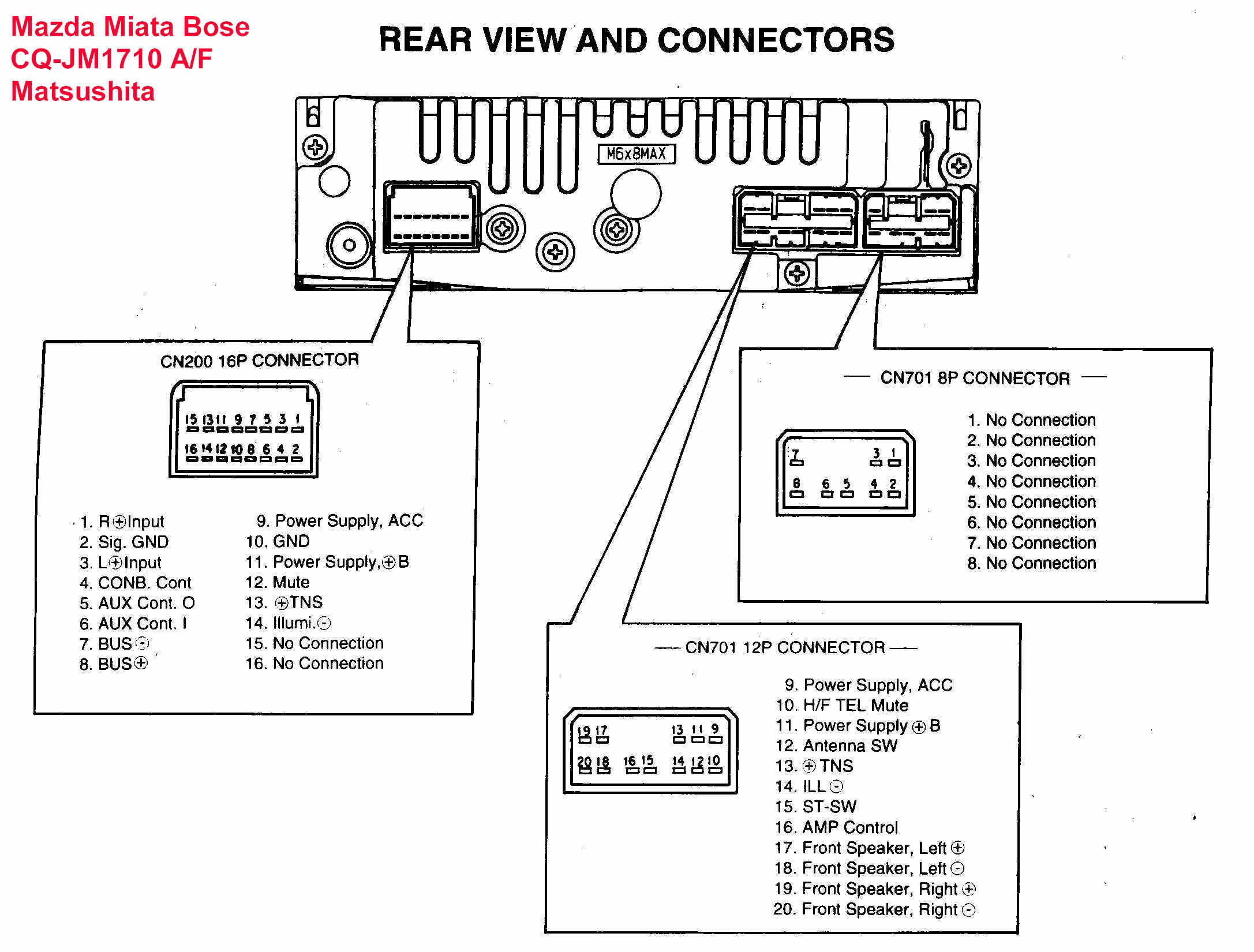
Wiring Harness Connectors
These diagrams will show all the connectors, with their pin assignments. This information is very useful if you are trying to install or remove the amplifier. You need to know which wire goes to which pin.
Special Bose Features
Bose systems often integrate proprietary technologies, such as equalization circuits tailored to the specific vehicle interior. The diagram may include details about these circuits, including any filtering or signal processing components.
Decoding the Symbols
Wiring diagrams use a universal language of symbols to represent different components and connections. Here's a quick guide to some of the most common symbols you'll encounter:
- Solid lines: Represent wires. Thicker lines often indicate power wires.
- Dashed lines: May represent shielded cables or ground connections.
- Circles or dots: Indicate connection points.
- Resistors: Zigzag line.
- Capacitors: Two parallel lines.
- Ground symbol: Three lines decreasing in length, pointing downwards.
- Fuse: A squiggly line inside a rectangle.
- Connectors: Rectangles with pins. Pin numbers are usually indicated.
- Color codes: Wires are often identified by their color (e.g., RED, BLU, GRN). A key will typically be provided to decode these abbreviations.
Color codes are crucial. A typical example might be:
RED = +12V
BLK = Ground
WHT = Left Front (+)
GRY = Left Front (-)
GRN = Right Front (+)
BLU = Right Front (-)
How It Works: The Signal Path
Understanding how the audio signal flows through the system is key to interpreting the wiring diagram. Here's a simplified overview:
- The head unit (or other audio source) generates an audio signal.
- This signal travels to the amplifier via either high-level or low-level inputs.
- Inside the amplifier, the signal is boosted in power. This amplification process requires both a positive voltage (+12V) and a ground connection to the car chassis to create an electrical circuit. The remote turn-on wire acts like a switch, turning the amp ON and OFF.
- The amplified signal is then sent to the speakers via the output wires. Each speaker requires two wires: one positive and one negative.
- The speakers convert the electrical signal into sound waves.
Bose systems often incorporate additional processing within the amplifier, such as equalization or signal filtering. The wiring diagram will show where these components are located in the signal path.
Real-World Use: Basic Troubleshooting Tips
Armed with your wiring diagram, you can tackle some basic troubleshooting tasks:
- No sound: Check the power supply to the amplifier. Verify that the +12V, ground, and remote turn-on wires are properly connected and receiving voltage. Test the fuse.
- Weak sound: Inspect the speaker wires for damage or loose connections. Check the speaker impedance to ensure it's compatible with the amplifier.
- Distorted sound: Look for grounding issues. A poor ground connection can introduce noise and distortion into the signal. Inspect the RCA cables (if used) for damage.
- One speaker not working: Check the speaker wires and the speaker itself. Swap the speaker wires from the working speaker to the non-working speaker to confirm if the speaker is dead or not.
- Amp turns on, then off: This could indicate a short circuit or an overheating issue. Check the speaker wiring for shorts.
Always disconnect the negative terminal of your car battery before working on any electrical components to avoid accidental shorts.
Safety First: Identifying Risky Components
Working with car electronics involves certain safety risks. Be particularly careful around:
- The +12V wire: This wire carries high current and can cause a severe shock or fire if shorted to ground. Always disconnect the battery before working on this wire.
- Capacitors: Some capacitors can store a charge even after the power is disconnected. Use a resistor to discharge them before handling.
- Heat sinks: Amplifiers generate heat. Avoid touching the heat sinks while the amplifier is operating or immediately after it has been turned off.
If you are unsure about any aspect of the wiring, consult a qualified car audio technician. It's better to be safe than sorry when dealing with electrical systems.
With a little patience and the right knowledge, you can confidently navigate the complexities of Bose car amplifier wiring diagrams. Remember to always prioritize safety and double-check your work. Good luck!
We have access to a library of wiring diagrams. Contact us to download the specific Bose Car Amplifier Wiring Diagram for your vehicle.