
Factory Gm Wiring Harness Color Codes
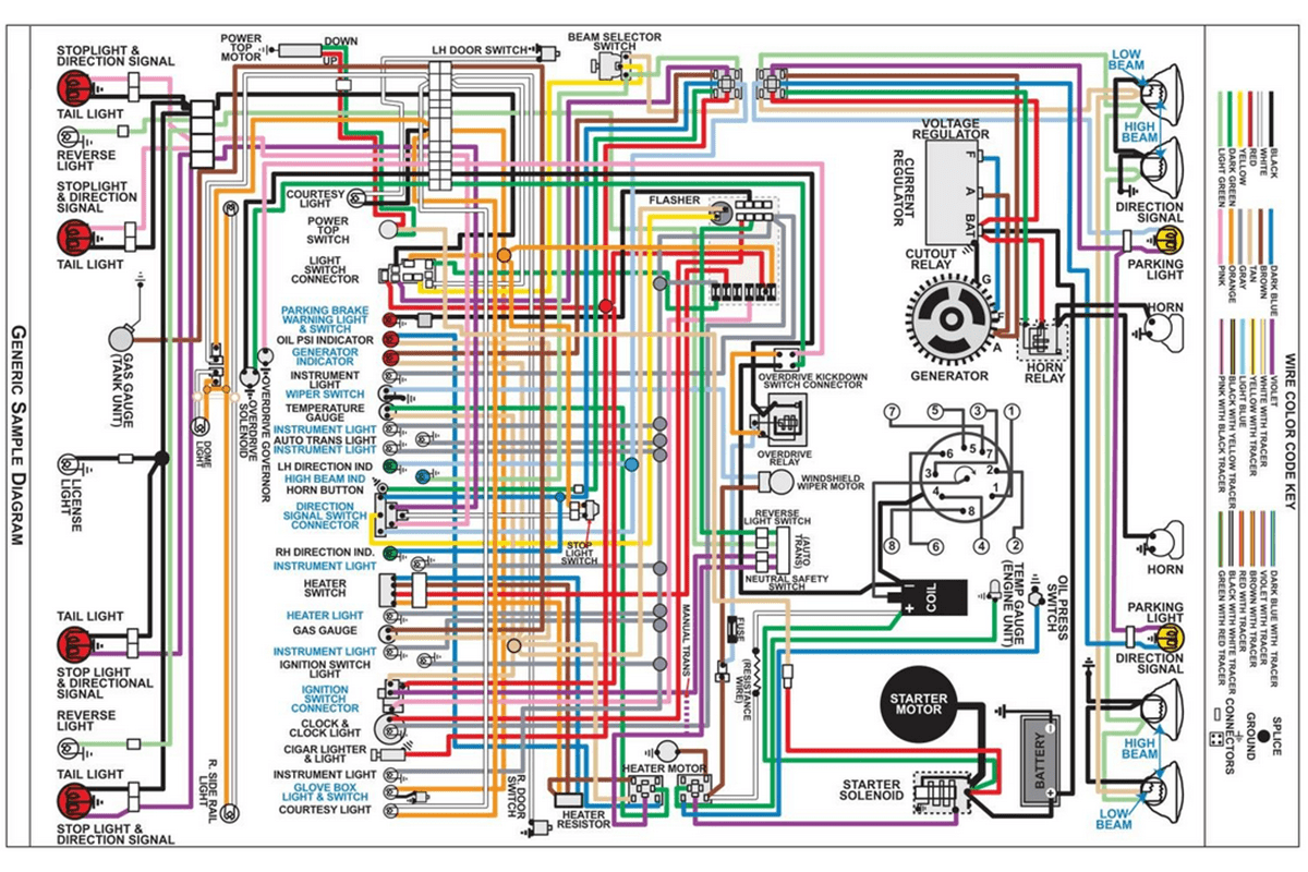
Understanding your General Motors (GM) wiring harness is crucial for successful automotive repairs, modifications, and diagnostics. This article serves as a comprehensive guide to GM wiring harness color codes, empowering you with the knowledge to navigate these complex systems like a seasoned professional. Knowing these codes can save you time, prevent costly mistakes, and ultimately give you more control over your vehicle's electrical system. Whether you're troubleshooting a faulty sensor, installing aftermarket accessories, or simply expanding your automotive expertise, deciphering the color-coded language of GM wiring is an invaluable skill.
Why Understanding GM Wiring Harness Color Codes Matters
The ability to interpret GM wiring diagrams and identify wires by color code unlocks a range of possibilities:
- Accurate Repairs: Identify damaged or disconnected wires quickly, leading to faster and more effective repairs. Avoid the frustration of guessing and testing every wire.
- Safe Modifications: When adding aftermarket accessories (lights, stereos, alarms), understanding the existing wiring prevents accidental shorts, damage to the vehicle's electrical system, and even fires.
- Efficient Diagnostics: Pinpoint electrical problems with greater precision, reducing diagnostic time and minimizing unnecessary parts replacement.
- Learning Opportunity: Gaining proficiency in wiring diagrams and color codes significantly enhances your overall automotive knowledge and troubleshooting abilities.
Key Specifications and Main Parts of a GM Wiring Harness
A typical GM wiring harness consists of several key components working together to distribute power and signals throughout the vehicle:
Wiring
The foundation of the harness, wires are typically made of stranded copper for flexibility and conductivity. The gauge (thickness) of the wire is crucial; thicker wires carry more current. GM uses the American Wire Gauge (AWG) standard to measure wire thickness. Lower AWG numbers indicate thicker wires. Each wire is insulated with a colored coating, which brings us to the heart of this discussion – the color code.
Connectors
Connectors provide a secure and reliable way to join wires and components. They come in various shapes and sizes, often keyed to prevent accidental misconnections. Inside the connector, metal terminals crimp onto the wires, ensuring a good electrical connection. Common connector types include Weatherpack, Metri-Pack, and Delphi connectors. Good quality connectors are vital for long term reliability.
Terminals
These are the metal contacts that crimp or solder onto the ends of wires, allowing them to connect to connectors or other electrical components. The quality of the crimp is paramount for a reliable connection. A loose or corroded terminal can cause intermittent electrical problems that are difficult to diagnose. Crimp tools designed specifically for automotive terminals are highly recommended.
Ground Straps
These are heavy-gauge wires or braided straps that connect the vehicle's chassis to the engine, body, and other components, providing a common ground (or earth) point. A good ground is essential for the proper operation of all electrical systems. Corroded or loose ground straps are a frequent source of electrical problems.
Protective Sheathing and Tape
To protect the wires from abrasion, heat, and moisture, wiring harnesses are typically wrapped in protective sheathing, such as corrugated tubing, or wrapped with specialized electrical tape. This sheathing also helps to bundle the wires together, keeping the harness organized and preventing it from interfering with moving parts.
Fuses and Relays
Although technically not *part* of the harness, fuses and relays are *integral* to the circuits the harness carries. Fuses protect circuits from overcurrent, while relays act as electrically controlled switches, allowing a low-current circuit to control a high-current circuit. These are vital protection and control components.
Understanding GM Wiring Color Codes and Symbols
GM utilizes a standardized color-coding system to identify the function of each wire within the harness. While variations exist between model years and vehicle platforms, some colors are consistently associated with specific functions. Here's a breakdown of commonly used colors and their typical applications:
- Red: Typically indicates a constant 12V power source, often directly from the battery.
- Orange: Usually signifies an accessory power source, which is only active when the ignition switch is in the "accessory" or "run" position.
- Yellow: Often used for ignition power, active when the ignition switch is in the "run" or "start" position.
- Pink: Another common color for ignition power, may also be used for certain sensor circuits.
- Black: Universally used for ground connections.
- White: Can represent various functions, often used for lighting circuits or signal wires.
- Blue: Frequently used for lighting circuits, such as headlights or turn signals.
- Green: Commonly used for lighting circuits, such as tail lights or brake lights.
- Brown: Can indicate switched ground or various signal wires.
- Gray: Often used for instrument panel lighting or sensor signals.
- Purple: Typically used for starter solenoid circuits.
Stripes: Wires may also have a stripe of a different color running along their length. This stripe further identifies the wire's specific function within a circuit. For example, a red wire with a white stripe may indicate a specific power supply to a particular module.
Symbols on Wiring Diagrams: Wiring diagrams use various symbols to represent electrical components. Some common symbols include:
- A circle with an "X" inside represents a connector.
- A zig-zag line indicates a resistor.
- A coil symbol indicates a solenoid or relay coil.
- A triangle pointing towards a line represents a diode.
- A ground symbol represents a connection to the vehicle's chassis.
Lines on the diagram represent wires. Thicker lines often denote wires carrying more current (higher amperage). Dashed lines might indicate shielded wires or communication buses (like CAN bus).
Always refer to the specific wiring diagram for your vehicle's year, make, and model for accurate information. Generic color codes can be helpful, but specific circuits can vary.
How It Works: Following the Circuit
To understand how a circuit works, start by identifying the power source (usually a red or orange wire). Follow the wire through the circuit, noting any switches, relays, fuses, and components it passes through. Trace the path to the ground (black wire). The circuit is complete when power flows from the source, through the components, and back to ground. If any part of this path is broken (e.g., a blown fuse, a disconnected wire, a faulty switch), the circuit will not function.
Real-World Use: Basic Troubleshooting Tips
Here are a few basic troubleshooting tips using your knowledge of GM wiring color codes:
- No Power to an Accessory: Check the orange wire supplying power to the accessory. Use a multimeter to verify that it has 12V when the ignition is in the "accessory" or "run" position. If not, check the fuse associated with that circuit.
- Faulty Ground Connection: A common cause of electrical problems is a poor ground connection. Check the black wire associated with the faulty component. Ensure it is securely connected to the vehicle's chassis and that the connection is clean and free of corrosion.
- Intermittent Lighting Problems: Trace the blue, green, or white wires associated with the lighting circuit. Look for loose connectors, damaged wires, or corroded terminals.
When troubleshooting, always use a multimeter to test for voltage, continuity, and resistance. A multimeter is your best friend when diagnosing electrical problems.
Safety First: Handling Risky Components
Working with automotive electrical systems can be dangerous. Always take the following precautions:
- Disconnect the Battery: Before working on any electrical component, disconnect the negative (-) battery cable to prevent accidental shorts and electrical shocks.
- Avoid Working on Live Circuits: If you must work on a live circuit, use extreme caution and wear appropriate safety gear, such as insulated gloves.
- Identify Airbag Circuits: Airbag circuits contain explosive devices. Never probe or tamper with these circuits without proper training and precautions. Accidental deployment can cause serious injury. Typically these wires are YELLOW.
- Fuel Injection Systems: Be extremely cautious when working near fuel injection systems. Fuel is highly flammable. Avoid creating sparks or heat near fuel lines or components.
- Capacitors: Be mindful of capacitors in electronic modules. These can store a charge even after the battery is disconnected. Allow ample time for capacitors to discharge before touching any components inside the module.
High-Voltage Systems (Hybrid/Electric Vehicles): Working on hybrid or electric vehicles involves extremely high voltages that can be lethal. Do not attempt to work on these systems unless you have been specifically trained and certified to do so.
Remember: when in doubt, consult a qualified automotive electrician.
We have a detailed GM wiring diagram available for download, encompassing a wide range of models and years. This diagram will serve as an invaluable resource for your automotive endeavors, providing you with the information you need to confidently tackle electrical repairs and modifications.