Factory Radio Gm Wiring Harness Color Codes
Understanding your GM factory radio wiring harness color codes is crucial for various automotive tasks, from simply replacing a blown fuse to upgrading your entire sound system. Whether you're a seasoned DIYer or just starting to delve into the world of car audio, this guide will provide you with the knowledge to confidently navigate the intricate web of wires behind your GM radio. Having a clear understanding minimizes the risk of damaging your vehicle's electrical system and ensures a successful and safe project.
Why Understanding GM Radio Wiring Matters
Why bother learning about these color codes? There are several compelling reasons:
- Radio Replacement or Upgrade: The most common scenario. Swapping out your old factory radio for a new one, either aftermarket or a newer GM model, requires connecting the appropriate wires.
- Speaker Installation: Upgrading your speakers demands knowing which wires power each individual speaker. This allows you to connect new speakers correctly, ensuring proper phasing and sound quality.
- Amplifier Installation: Adding an external amplifier requires tapping into the existing speaker wires or using the radio's low-level outputs (if available). Identifying these wires is critical.
- Wiring Repairs: Over time, wires can become damaged or corroded. Knowing the color codes allows you to quickly identify and repair the affected wires.
- Adding Accessories: Some accessories, like backup cameras or steering wheel control interfaces, integrate with the factory radio wiring. Understanding the connections simplifies the installation process.
- Diagnostic Troubleshooting: If your radio isn't working correctly, understanding the wiring can help you isolate the problem.
Key Specs and Main Parts of the GM Radio Wiring Harness
The GM radio wiring harness is essentially a standardized set of wires that connect the radio to the vehicle's electrical system. It typically consists of two main connectors: the power/speaker connector and the data/accessory connector. The power/speaker connector handles the power supply, ground, and speaker outputs. The data/accessory connector carries signals for features like steering wheel controls, vehicle speed sensor (VSS), and illumination. Note that the specific pinout (the arrangement of pins in the connector) and the colors assigned to each function can vary slightly depending on the year, make, and model of your GM vehicle, as well as the radio model itself. Therefore, it is essential to consult a wiring diagram specific to *your* vehicle.
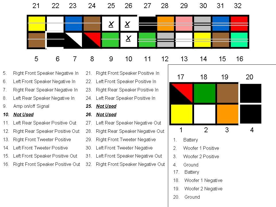
Here's a breakdown of some common wire color codes and their functions (Note: Always verify with a diagram specific to your car!):
- Yellow: Constant +12V Power (Memory). This wire provides power to the radio even when the ignition is off, preserving settings and presets.
- Red: Switched +12V Power (Ignition). This wire provides power to the radio only when the ignition is turned on.
- Black: Ground. Provides the necessary ground connection for the radio to function.
- Gray: Right Front Speaker Positive (+).
- Green: Left Front Speaker Positive (+).
- White: Left Front Speaker Negative (-).
- Violet: Right Front Speaker Negative (-).
- Gray/Black Stripe: Right Front Speaker Negative (-).
- Green/Black Stripe: Left Front Speaker Negative (-).
- Dark Green: Left Rear Speaker Positive (+).
- Light Green: Right Rear Speaker Positive (+).
- Dark Blue: Left Rear Speaker Negative (-).
- Brown: Right Rear Speaker Negative (-).
- Orange: Illumination (Dimmer). This wire dims the radio's display when the headlights are turned on.
- Pink: Vehicle Speed Sensor (VSS). Used by some radios for speed-sensitive volume control.
- Dark Blue/White Stripe: Remote Amplifier Turn-On (if applicable). Sends a +12V signal to turn on an external amplifier when the radio is powered on.
Understanding Wiring Diagram Symbols
Wiring diagrams utilize a standardized set of symbols to represent different electrical components and connections. Here's a quick overview:
- Solid Lines: Represent wires. The thickness of the line may indicate the wire gauge (thickness).
- Dashed Lines: May represent shielding or a connection that is not always present.
- Circles: Often represent connectors or terminals.
- Squares: May represent components like relays or fuses.
- Triangles: Can represent amplifiers or signal direction.
- Color Codes: Are typically written next to the wires or indicated in a legend. Common abbreviations include:
- BLK: Black
- RED: Red
- YEL: Yellow
- GRN: Green
- BLU: Blue
- WHT: White
- ORG: Orange
- BRN: Brown
- Abbreviations for color stripes may also be used. For example, GRN/BLK indicates a green wire with a black stripe.
Pay close attention to the ground symbols. These indicate where a wire is connected to the vehicle's chassis, providing a ground path for the electrical circuit.
How It Works: A Simplified Explanation
The factory radio wiring harness acts as the central nervous system for your car's audio system. It channels power from the battery, distributes it to the radio, and then sends audio signals to the speakers. The yellow wire provides constant power to maintain the radio's memory (presets, settings, etc.). The red wire provides switched power, turning the radio on and off with the ignition. The black wire provides a ground connection, completing the electrical circuit. The speaker wires transmit the amplified audio signal from the radio to the individual speakers.
Signals from steering wheel controls (if equipped) are transmitted through the data connector, allowing you to adjust the radio's volume, change channels, and perform other functions without taking your hands off the wheel. The illumination wire dims the radio's display when the headlights are turned on, preventing glare at night. The VSS wire, if present, provides the radio with information about the vehicle's speed, allowing for features like speed-sensitive volume control.
Real-World Use: Basic Troubleshooting Tips
Here are a few basic troubleshooting tips using the wiring diagram:
- No Power to Radio:
- Check the yellow and red wires for +12V using a multimeter. If either wire lacks power, check the corresponding fuse in the fuse box.
- Verify the black wire has a good ground connection. Use a multimeter to check continuity between the black wire and the vehicle's chassis.
- No Sound from Speakers:
- Check the speaker wires for continuity using a multimeter. A broken wire will result in no continuity.
- Ensure the speaker wires are properly connected to the speakers.
- Inspect the speakers themselves for damage.
- Radio Turns On and Off Intermittently:
- Check the connections to the yellow and red wires for looseness or corrosion.
- Inspect the wiring harness for any signs of damage, such as frayed wires or cracked insulation.
Important: Always disconnect the negative battery terminal before working on any electrical components in your vehicle to prevent electrical shocks and damage to your vehicle's electrical system.
Safety First: Highlighting Risky Components
Working with automotive electrical systems involves inherent risks. The most significant risk is electrical shock. Always disconnect the negative battery terminal before working on any electrical components. Fuses are designed to protect the electrical system from overloads. Never replace a fuse with a higher amperage fuse, as this can damage the wiring and potentially cause a fire. Capacitors, especially those found in older radios, can store a charge even after the radio has been disconnected from power. Discharge capacitors before handling them to avoid electrical shock.
Incorrect wiring can lead to short circuits, which can damage the radio, the vehicle's electrical system, or even cause a fire. Double-check all connections before powering on the radio. If you are unsure about any aspect of the wiring, consult a qualified automotive electrician.
We have a downloadable wiring diagram file available for common GM vehicles to help you with your project. You can access it [link to download]. Remember to always verify the diagram against your specific vehicle's year, make, and model.