Factory Tail Light Wiring Color Code
Understanding your factory tail light wiring color code is crucial for a variety of automotive tasks, ranging from simple bulb replacements to complex electrical troubleshooting and custom modifications. This guide is designed to equip the intermediate car owner, modder, or DIY mechanic with the knowledge necessary to confidently navigate the sometimes-intimidating world of automotive electrical systems.
Purpose: Why Understanding Tail Light Wiring Matters
Why bother diving into the labyrinthine world of tail light wiring? The answer is multifaceted. Having a solid grasp of the color codes and circuit layouts empowers you to:
- Perform Accurate Repairs: When a tail light malfunctions, knowing the wire responsible for each function (brake, turn signal, running light) allows you to pinpoint the problem quickly and efficiently.
- Install Aftermarket Accessories Safely: Adding LED upgrades, trailer light connectors, or even custom lighting features requires a clear understanding of the existing wiring. Incorrect connections can lead to blown fuses, damaged components, or even electrical fires.
- Troubleshoot Electrical Issues Systematically: If your tail lights are behaving erratically, a knowledge of the wiring diagram is essential for tracing the fault back to its source, whether it's a faulty ground, a broken wire, or a malfunctioning switch.
- Enhance Your Automotive Knowledge: Even if you don't plan on performing any immediate repairs, understanding the principles behind tail light wiring expands your general automotive knowledge and makes you a more informed car owner.
Key Specs and Main Parts
Before we delve into the intricacies of color codes, let's outline the key components involved in a typical tail light system:
- Power Source (Battery): Provides the initial electrical energy for the entire system.
- Fuses: Protective devices that interrupt the circuit if the current exceeds a safe level. A blown fuse is often the first indication of a problem.
- Wiring Harness: A bundle of wires, each with a specific color code, that connects all the components of the tail light system.
- Light Switch: Activates the running lights, which also illuminate the tail lights.
- Brake Light Switch: Activated when the brake pedal is pressed, sending power to the brake lights.
- Turn Signal Switch (Flasher Unit): Controls the flashing of the turn signal lights. The flasher unit is a crucial component responsible for interrupting the current flow at a regular interval, creating the flashing effect.
- Tail Light Assembly: The physical housing that contains the bulbs and reflectors.
- Bulbs: The light-emitting components (incandescent, halogen, or LED) that illuminate the tail lights.
- Ground Connection: Provides a return path for the electrical current back to the battery. A poor ground is a common cause of tail light problems.
Key Specs: Voltage in automotive tail light systems is typically 12V DC (Direct Current). Wire gauge (thickness) is important; thinner wires can handle less current and may overheat if overloaded. Consult your vehicle's service manual for the appropriate wire gauge for each circuit.
Symbols: Decoding the Wiring Diagram
Wiring diagrams use standardized symbols to represent electrical components and connections. Understanding these symbols is crucial for interpreting the diagram correctly. Here's a breakdown of some common symbols you'll encounter:
- Solid Lines: Represent wires. The thickness of the line sometimes indicates the wire gauge, but this is not always consistent.
- Dotted Lines: Often represent ground connections or shielded wires.
- Circles: Typically represent light bulbs.
- Rectangles: Can represent various components, such as switches, relays, or control modules. The specific function is usually labeled inside the rectangle.
- Zigzag Lines: Represent resistors.
- Ground Symbol (Usually three horizontal lines decreasing in length): Indicates a connection to the vehicle's chassis, providing a return path for the electrical current. A good ground is essential for proper circuit operation.
- Connectors: Shown as interlocking shapes, indicating where wires can be disconnected.
Color Codes: This is where the "color code" comes in. Each wire is assigned a specific color (or a combination of colors) to identify its function. While there isn't a universal standard across all manufacturers and models, some common color codes exist. Always refer to your vehicle's specific wiring diagram for accurate information. Common colors include:
- Black: Typically ground.
- Red: Often used for circuits powered directly from the battery.
- Brown: Usually for tail lights (running lights).
- Yellow: Often used for turn signals.
- Green: May be used for brake lights or turn signals.
- White: Can be used for various functions, including reverse lights.
It's crucial to remember that these are just general guidelines. Always consult your vehicle's specific wiring diagram to avoid misidentification.
How It Works: Following the Circuit
The tail light system operates as a series of interconnected circuits. When you turn on your headlights, the light switch closes, sending power through the wiring harness to the tail light assembly. This activates the running lights. When you press the brake pedal, the brake light switch closes, sending power to the brake light circuit, which illuminates the brake lights. When you activate the turn signal, the turn signal switch and flasher unit work together to intermittently send power to the corresponding turn signal bulb, creating the flashing effect. The flasher unit uses a bimetallic strip that heats up and cools down, causing it to open and close the circuit repeatedly. This creates the familiar clicking sound and the flashing light.
Each circuit requires a complete path for the electricity to flow. This means that the power must travel from the battery, through the switch, through the bulb, and back to the battery via the ground connection. A break in any part of this circuit will prevent the light from working. This principle is the foundation of troubleshooting.
Real-World Use: Basic Troubleshooting Tips
Here are some basic troubleshooting tips you can use to diagnose tail light problems:
- Check the Bulbs: Start with the obvious. A burnt-out bulb is the most common cause of tail light failure.
- Check the Fuses: Use a multimeter to test the continuity of the fuse. A blown fuse indicates a short circuit or an overload in the system. Replace the fuse with one of the same amperage rating.
- Check the Ground Connection: Ensure that the ground connection is clean and secure. A corroded or loose ground can prevent the lights from working properly. Clean the ground connection with a wire brush and tighten the bolt.
- Use a Multimeter: A multimeter is your best friend for electrical troubleshooting. Use it to check for voltage at the bulb socket and to test the continuity of the wires.
- Inspect the Wiring Harness: Look for damaged, frayed, or corroded wires. Repair or replace any damaged wires.
- Consult the Wiring Diagram: Refer to your vehicle's wiring diagram to identify the specific wires and connections involved in the circuit.
Example: If your left turn signal is not working, but the right one is, check the bulb, the fuse for the left turn signal circuit, the ground connection for the left tail light assembly, and the wiring between the turn signal switch and the left tail light. The wiring diagram will help you identify the correct wires to test.
Safety: Highlight Risky Components
Working with automotive electrical systems can be dangerous if you're not careful. Here are some safety precautions to keep in mind:
- Disconnect the Battery: Always disconnect the negative battery terminal before working on any electrical system. This will prevent accidental short circuits and electrical shocks.
- Use Insulated Tools: Use tools with insulated handles to protect yourself from electrical shock.
- Avoid Working in Wet Conditions: Water is an excellent conductor of electricity, so avoid working on electrical systems in wet conditions.
- Properly Identify Wires: Always double-check the wiring diagram to ensure you're working with the correct wires. Incorrect connections can damage components or create dangerous situations.
- Be Aware of Airbags: Some wiring harnesses run near airbag components. Be extremely careful when working in these areas, as accidental deployment of an airbag can cause serious injury.
Warning: Never bypass a fuse. Fuses are designed to protect the electrical system from overloads. Bypassing a fuse can lead to a fire. Also, always replace a blown fuse with one of the same amperage rating.
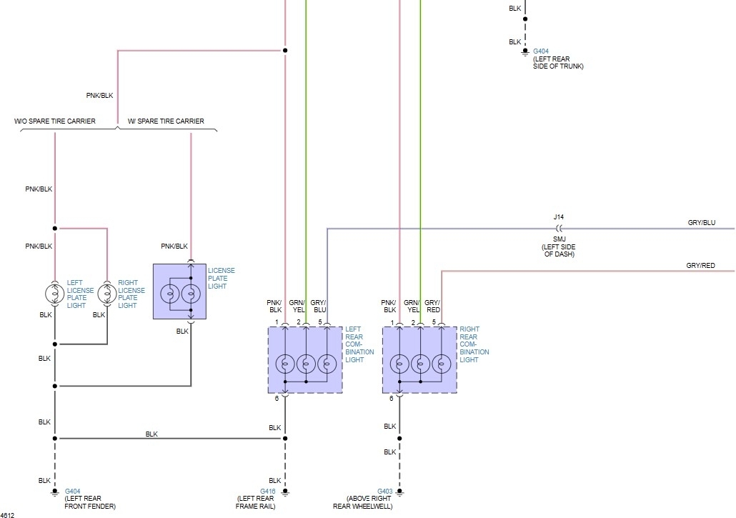
To help you even further with your tail light wiring endeavors, we have a general factory tail light wiring diagram file available for download. While it's not vehicle-specific, it provides a great overview of the common components and their interconnections. Remember, always supplement this with your vehicle's unique wiring diagram for accurate information.