Factory Wiring Harness Color Code Nissan Radio Wiring Diagram
Understanding the factory wiring harness color code for your Nissan radio is crucial whether you're upgrading your stereo, diagnosing audio problems, or simply learning more about your vehicle's electrical system. A Nissan radio wiring diagram is essentially a roadmap to your car's audio connections. This article breaks down the Nissan radio wiring diagram, color codes, and troubleshooting tips to help you navigate your car's audio system with confidence.
Why a Nissan Radio Wiring Diagram Matters
A Nissan radio wiring diagram provides a visual representation of how the radio is connected to the car's electrical system. Its importance stems from several key areas:
- Repairs: Quickly identify damaged or disconnected wires causing audio issues.
- Upgrades: Connect aftermarket stereos, amplifiers, or speakers correctly without damaging the factory wiring.
- Troubleshooting: Pinpoint the source of problems like a non-functional radio, speaker malfunctions, or power issues.
- Learning: Gain a better understanding of automotive electrical systems and how components interact.
Trying to modify or repair your car's audio system without a diagram is like navigating a maze blindfolded – you're likely to get lost and potentially cause significant damage. It's a necessary tool for any serious car audio enthusiast.
Key Specs and Main Parts of a Nissan Radio Wiring Harness
The Nissan radio wiring harness connects the radio unit to the car's power supply, speakers, antenna, and other control systems. Understanding its components is key to interpreting the wiring diagram:
- Power Wires: Typically, a red wire for the constant 12V power (keeps radio memory alive), and a yellow wire for switched 12V power (turns the radio on/off with the ignition). There is also usually a ground wire, typically black or brown.
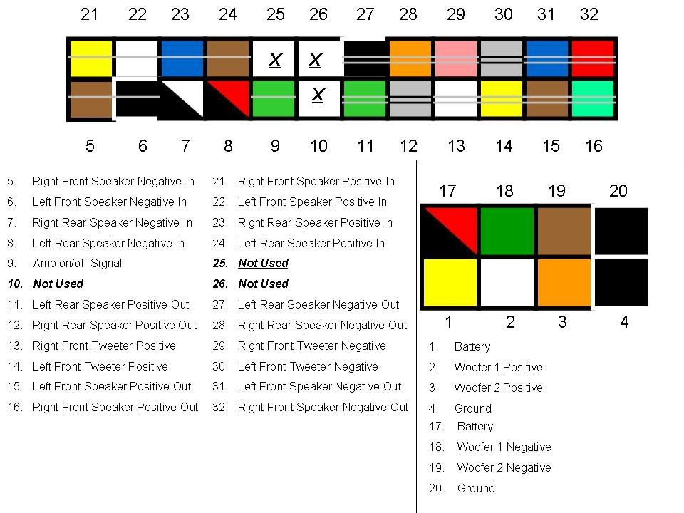
- Speaker Wires: These wires connect the radio to the speakers. Each speaker (front left, front right, rear left, rear right) has a positive (+) and a negative (-) wire. Nissan typically uses a color-coded scheme for these.
- Antenna Wire: Usually a coaxial cable, often with a specific connector, that receives radio signals.
- Illumination Wire: This wire dims the radio display when the headlights are turned on. Often orange or white with a colored stripe.
- Remote Turn-On Wire (Amp Turn-On): A blue or blue/white wire used to signal external amplifiers to power on. It's activated when the radio is turned on.
- CAN Bus Wires (in newer models): Some newer Nissans use a CAN (Controller Area Network) bus system to transmit data. These wires, often two twisted wires, allow the radio to communicate with other vehicle systems.
Important Note: The exact color codes can vary slightly depending on the specific Nissan model and year. Always consult the specific wiring diagram for your vehicle.
Decoding the Symbols and Color Codes
A Nissan radio wiring diagram uses a standardized set of symbols and color codes to represent the various components and connections. Learning to interpret these is essential for understanding the diagram:
Lines:
- Solid Lines: Represent wires.
- Dashed Lines: May represent shielding or connections to ground.
- Arrows: Indicate the direction of current flow.
Colors:
The color codes are crucial for identifying each wire's function. Here's a general guide, but always refer to your specific diagram:
- Red: Constant 12V Power.
- Yellow: Switched 12V Power (Ignition).
- Black: Ground.
- White: Often used for speaker wires (check specific function with stripe color).
- Gray: Typically used for speaker wires.
- Green: Typically used for speaker wires.
- Violet/Purple: Often used for speaker wires.
- Blue: Remote Turn-On (Amplifier).
- Orange: Illumination.
- Brown: Ground (sometimes).
Many wires will have a main color and a stripe color (e.g., "White/Blue"). This further distinguishes the wire's function. The first color is the main wire color, and the second is the stripe.
Icons:
- Circles: Often represent connection points or terminals.
- Squares: Can represent fuses or relays.
- Speaker Symbol: Indicates speaker connections.
- Ground Symbol: Indicates a connection to the chassis ground.
How It Works: Tracing the Circuits
The radio receives power from the battery via the red (constant 12V) and yellow (switched 12V) wires. The red wire provides power to maintain radio settings (like presets) even when the ignition is off. The yellow wire supplies power to operate the radio when the ignition is turned on.
When the radio is powered on, it sends audio signals to the speakers through the speaker wires. Each speaker requires two wires: a positive (+) and a negative (-). The radio amplifies the audio signal and sends it to the speakers, which convert the electrical signal into sound waves.
The antenna wire receives radio signals. The radio processes these signals to extract the audio information.
The illumination wire dims the radio's display when the headlights are turned on, preventing the screen from being too bright at night.
The remote turn-on wire activates external amplifiers. When the radio is turned on, this wire sends a 12V signal to the amplifier, telling it to power on. This prevents the amplifier from drawing power when the radio is off.
Real-World Use: Basic Troubleshooting Tips
Here are some basic troubleshooting scenarios using the wiring diagram:
- No Power to Radio: Check the red and yellow wires with a multimeter to ensure they are receiving 12V. Also, check the ground wire for a good connection to the chassis. Verify the fuses connected to these circuits.
- No Sound from Speakers: Check the speaker wire connections. Ensure the wires are properly connected to the speakers and the radio. Use a multimeter to check for continuity in the speaker wires. Test the speakers themselves by swapping them or testing them with a known good audio source.
- Dim Radio Display: Verify the illumination wire connection. If the headlights are on and the display is not dimming, check the voltage on the illumination wire when the headlights are on.
- Antenna Issues: Inspect the antenna wire connection. Make sure it is securely connected to the radio and the antenna.
Safety First: Handling Risky Components
Working with automotive electrical systems can be dangerous. Here are some essential safety precautions:
- Disconnect the Battery: Before working on any electrical components, disconnect the negative terminal of the battery to prevent short circuits and electrical shock.
- Use a Multimeter: Use a multimeter to test for voltage and continuity before making any connections. This will help you avoid accidentally shorting circuits or damaging components.
- Work in a Well-Lit Area: Ensure you have adequate lighting to see the wiring clearly.
- Wear Safety Glasses: Protect your eyes from sparks or debris.
- Be Aware of Airbags: Some wiring may be located near airbag modules. Avoid disconnecting or tampering with these modules unless you are specifically trained to do so. Airbags can deploy unexpectedly and cause serious injury.
- Fuses are Important: Never replace a fuse with a higher amperage fuse. This can overload the circuit and cause a fire.
Working on electrical systems can cause damage if done incorrectly. Seek professional assistance from a certified mechanic or installer if you are uncertain about any procedure.
We have a sample Nissan Radio Wiring Diagram file available for download. With this diagram and the information provided in this article, you will be well-equipped to troubleshoot and upgrade your Nissan's audio system.