Factory Wiring Harness Color Vw Radio Wiring Diagram
Volkswagen (VW) radio wiring diagrams, especially those outlining the factory wiring harness color codes, are indispensable resources for anyone working on their car's audio system. Whether you're tackling a repair, upgrading to a new head unit, adding amplifiers, or simply trying to understand how your sound system is wired, having a clear and accurate diagram is crucial. Trying to guess or rely on memory can lead to short circuits, damaged components, or frustrating hours of troubleshooting. In this article, we'll break down the key elements of a VW radio wiring diagram, focusing on factory harness color codes, and provide practical guidance for using it effectively and safely.
Purpose and Importance
The primary purpose of a VW radio wiring diagram is to provide a visual representation of how the radio and related components are connected within the vehicle's electrical system. This includes the power supply, ground, speakers, antenna, and any auxiliary inputs or outputs. Having this diagram is essential for:
- Radio Replacement: When installing a new aftermarket head unit, you need to know which wires from the VW's factory harness correspond to the correct wires on the new radio's harness.
- System Upgrades: Adding amplifiers, subwoofers, or other audio components requires tapping into the existing wiring. The diagram identifies the appropriate wires for signal and power.
- Troubleshooting: If your radio isn't working correctly, the diagram helps you trace the circuit and identify potential points of failure, such as a blown fuse or a disconnected wire.
- Learning and Understanding: Even if you're not actively working on your car, studying the diagram can help you understand how your car's audio system is designed and how different components interact.
Key Specs and Main Parts
A typical VW radio wiring diagram, like the one we have available for download, will include the following key specifications and parts:
- Power Wires: Typically include a constant 12V+ wire (for memory and clock), a switched 12V+ wire (activated by the ignition), and a ground wire. The constant wire keeps the radio's memory alive even when the ignition is off.
- Speaker Wires: Usually consisting of four pairs of wires, each pair corresponding to a speaker (front left, front right, rear left, rear right). These wires are usually twisted pairs to help prevent interference.
- Antenna Wire: A single wire that connects to the antenna, typically a coaxial cable with a specialized connector.
- Illumination Wire: Dims the radio display when the headlights are turned on. This wire is connected to the vehicle's lighting circuit.
- Remote Turn-On Wire (Amplifier): A 12V+ output that turns on aftermarket amplifiers when the radio is powered on. This prevents the amplifier from draining the battery when the car is off.
- CAN Bus Wires: (In newer models) Car Area Network, allows different components in the car to talk to each other. Used for steering wheel controls or display of radio information on the dashboard screen.
- Factory Amplifier: Many VWs come with factory amplifiers. The diagram will indicate the location of the amplifier and how it's connected to the radio and speakers.
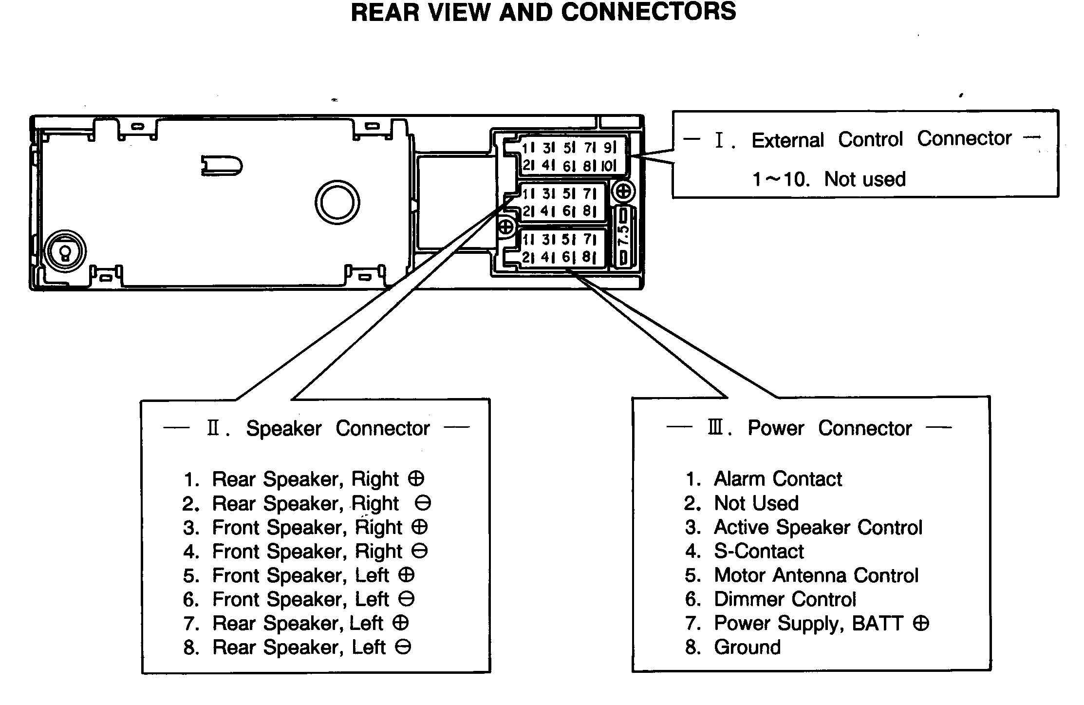
- Connector Pinouts: This shows the arrangement of the wires in the radio connector. It is vital when working with the wiring.
Symbols – Lines, Colors, and Icons
Understanding the symbols used in a wiring diagram is crucial for interpreting the information correctly.
- Lines: Solid lines represent wires. Dashed lines may indicate shielded cables or wires that are part of a data bus (like the CAN bus). The thickness of the line doesn’t usually indicate wire gauge, it is only for visual clarity.
- Colors: Color coding is *essential* in VW wiring diagrams. Each wire is assigned a specific color, and this color is indicated on the diagram. Common colors include red (power), black (ground), yellow (constant power), blue (remote turn-on), and various colors for the speaker wires (e.g., white, gray, green, purple, often with a stripe). VW uses a coding system where the first letter indicates the main color and the second letter the color of the stripe. For example, "sw/rt" is a black wire with a red stripe (Schwarz/Rot in German). You must use a good wire stripper to maintain the color coding on the wires.
- Icons: Different icons represent different components. Common icons include:
- Battery: Represented by a stylized battery symbol.
- Ground: Represented by a series of downward-pointing lines or a triangle.
- Fuse: Represented by a zig-zag line within a rectangle.
- Speaker: Represented by a circle with a cone shape inside.
- Radio: Typically represented by a rectangle with some internal components shown.
Carefully studying the color codes and symbols on the diagram will allow you to confidently identify and trace the different circuits in your car's audio system.
How It Works
The wiring diagram essentially maps the electrical circuits within the radio system. It illustrates how power flows from the battery, through fuses and switches, to the radio. It also shows how the radio is grounded to the car's chassis.
When the ignition is turned on, the switched 12V+ wire provides power to the radio, turning it on. The radio then sends audio signals to the speakers through the speaker wires. The remote turn-on wire activates the amplifier (if present), boosting the audio signal before it reaches the speakers. The antenna wire receives radio signals from the antenna.
For vehicles with CAN bus systems, the radio communicates with other control modules in the car, allowing for features such as steering wheel controls, displaying radio information on the instrument cluster, and automatic volume adjustment based on vehicle speed. The CAN bus wiring will also be shown on the wiring diagram.
Real-World Use – Basic Troubleshooting Tips
Here are some basic troubleshooting tips using the wiring diagram:
- No Power to Radio: Check the fuses related to the radio (consult your owner's manual for fuse locations). Use a multimeter to check for voltage on the constant and switched 12V+ wires at the radio connector. Also check that the ground wire is properly grounded to the car's chassis.
- No Sound from Speakers: Verify that the speaker wires are properly connected to the radio and the speakers. Use a multimeter to check for continuity in the speaker wires. Inspect the speaker cone for damage. If only one speaker isn't working, swap its connection with a known good speaker to isolate the issue.
- Radio Turns Off Intermittently: Check for loose connections at the radio connector and the ground wire. Inspect the wiring harness for any signs of damage or corrosion. A faulty ignition switch can also cause intermittent power loss.
- Steering Wheel Controls Not Working: For vehicles with CAN bus systems, check the CAN bus wires for proper connection and continuity. A malfunctioning CAN bus module can also cause this issue. The aftermarket radio may require a special CAN bus adapter to correctly interface with the steering wheel controls.
Safety – Highlight Risky Components
Working with automotive electrical systems can be dangerous if proper precautions are not taken. Here are some safety tips:
- Disconnect the Battery: Always disconnect the negative terminal of the battery before working on the electrical system. This prevents accidental short circuits and potential electrocution.
- Work in a Well-Ventilated Area: Some electrical components can emit harmful fumes.
- Use Proper Tools: Use insulated tools to prevent short circuits. A good multimeter is essential for testing voltage and continuity. Use a proper wire stripper to avoid damaging the wires.
- Identify High-Current Circuits: Pay special attention to high-current circuits, such as the power wires for the radio and amplifier. These circuits can generate a lot of heat and potentially cause a fire if shorted. Always use properly sized fuses to protect these circuits.
- Avoid Working with Airbag Wires: Airbag wiring is typically bright yellow. Do not tamper with these wires unless you are a trained technician. Accidental deployment of an airbag can cause serious injury.
Always double-check your work and consult the wiring diagram before making any connections. If you are unsure about any aspect of the wiring, it is best to consult a professional.
We have the VW factory wiring harness color diagram file ready for you to download. This diagram provides a comprehensive overview of the radio wiring for various VW models. Having this resource at your fingertips can save you time and frustration when working on your car's audio system.