Fan Control Relay 20210 Honda Civic Wiring Diagram
Let's dive into the fan control relay wiring diagram for a 2021 Honda Civic. This is a crucial piece of information for anyone looking to diagnose cooling fan issues, perform electrical repairs, or even modify their Civic's cooling system. Understanding this diagram will empower you to troubleshoot problems with confidence and avoid costly trips to the mechanic.
Purpose
Why bother with this diagram? Well, it's your roadmap to understanding the electrical circuitry that controls your Civic's cooling fans. Whether your fans aren't turning on, running constantly, or behaving erratically, this diagram is essential. It helps you trace the circuit, identify faulty components, and perform accurate voltage and continuity tests. It's also invaluable for those planning to install aftermarket cooling solutions or integrate auxiliary fans.
Key Specs and Main Parts
The fan control system on a 2021 Civic is relatively straightforward, but understanding the key components is crucial.
- Engine Control Module (ECM): This is the brain of the operation. The ECM monitors engine temperature and other parameters, and then decides when to activate the cooling fans.
- Coolant Temperature Sensor (CTS): Provides temperature readings to the ECM. A faulty CTS can lead to incorrect fan operation.
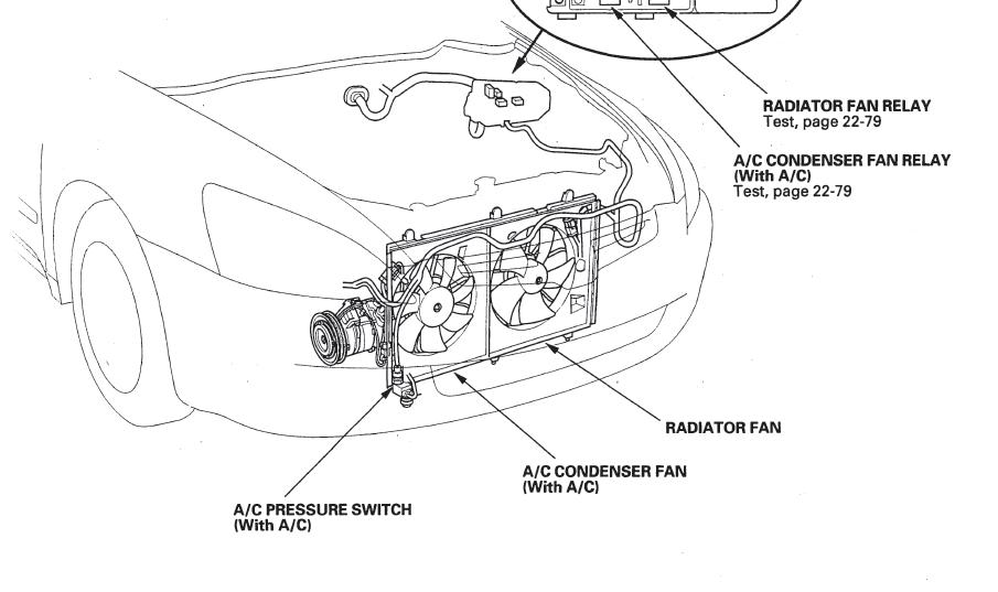
- Fan Control Relay(s): The relay acts as an electrically controlled switch. The ECM sends a small current to the relay's coil, which then closes the high-current circuit to power the fan motor. In some Civics, there may be multiple relays for low-speed and high-speed fan operation.
- Cooling Fan Motor(s): Self-explanatory – the motor that drives the fan blades to cool the radiator.
- Fuses: Protect the circuit from overcurrent. A blown fuse is often the first sign of a problem.
- Wiring Harness: The network of wires connecting all these components.
The 2021 Civic likely uses a multi-speed fan system, which means there will be at least two relays controlling the fans – one for low speed and one for high speed. The ECM determines which relay to activate based on the engine coolant temperature and other factors like A/C system demand.
Symbols – Decoding the Diagram
Wiring diagrams use a standardized set of symbols to represent components and connections. Here's a breakdown of the key symbols you'll encounter in the 2021 Civic's fan control relay diagram:
- Solid Lines: Represent wires. Thicker lines usually indicate power wires that carry higher current.
- Dashed Lines: Often represent ground connections or shielding.
- Color Codes: Wires are typically color-coded. Common colors include:
- Red: Often indicates a power wire connected directly to the battery (or a fused source).
- Black: Usually represents a ground wire.
- Blue/Yellow/Green: These often carry signals from sensors to the ECM or control signals to the relays. You'll need to refer to the specific color code legend in the diagram to be certain.
- Relay Symbol: A rectangle with a coil symbol (usually a looped wire) inside, and a switch symbol showing the normally open (NO) or normally closed (NC) contacts.
- Fuse Symbol: A wavy line inside a rectangle.
- Ground Symbol: A downward-pointing triangle or a series of horizontal lines.
- Connector Symbol: A circle or a small rectangle with numbers indicating the pin positions within the connector.
Understanding these symbols is essential for tracing the circuit and identifying connection points. Pay close attention to the color codes, as they are crucial for verifying wire connections.
How It Works
Here's a simplified explanation of how the 2021 Civic's fan control system operates:
- The Coolant Temperature Sensor (CTS) constantly monitors the engine coolant temperature and sends this information to the Engine Control Module (ECM).
- The ECM compares the CTS reading to pre-programmed thresholds.
- When the engine coolant temperature reaches a certain threshold (e.g., the low-speed fan activation temperature), the ECM sends a small voltage signal to the coil of the low-speed fan control relay.
- This voltage energizes the relay's coil, creating an electromagnetic field that pulls the relay's switch closed.
- Closing the relay switch completes the high-current circuit between the battery (via a fuse) and the low-speed cooling fan motor.
- The cooling fan motor turns on at low speed, helping to dissipate heat from the radiator.
- If the engine coolant temperature continues to rise, the ECM may activate the high-speed fan relay in a similar fashion.
- When the engine coolant temperature drops below a certain threshold, the ECM de-energizes the relay coil, the switch opens, and the fan turns off (or switches to a lower speed).
The A/C system can also influence fan operation. When the A/C is turned on, the ECM will often activate the cooling fans (either low or high speed) to help improve A/C performance, regardless of the engine coolant temperature.
Real-World Use – Basic Troubleshooting Tips
Here are some common problems and troubleshooting steps you can take using the wiring diagram:
- Fan Not Turning On:
- Check the fuse(s) for the cooling fan circuit. A blown fuse is a common cause.
- Check the fan control relay(s). You can try swapping relays with another similar relay in the fuse box to see if the problem is with the relay itself. You can also use a multimeter to test the relay's coil and contacts.
- Test the fan motor itself. You can directly apply 12V power to the fan motor to see if it spins. Be careful when doing this!
- Check the Coolant Temperature Sensor (CTS). A faulty CTS can send incorrect temperature readings to the ECM.
- If all of the above check out, the problem may lie with the ECM itself, or with the wiring harness. Use the wiring diagram to trace the circuit and check for broken or corroded wires.
- Fan Running Constantly:
- A stuck fan control relay is a likely culprit. Replace the relay.
- A faulty Coolant Temperature Sensor (CTS) can also cause this.
- Less likely, but possible, is a fault within the ECM.
Always use a multimeter to perform voltage and continuity tests. Refer to the wiring diagram to identify the correct test points and expected voltage levels.
Safety – Working with Electrical Systems
Working with electrical systems can be dangerous. Here are some essential safety precautions:
- Disconnect the negative battery terminal before working on any electrical components. This prevents accidental shorts and electrocution.
- Be careful around the cooling fan motor itself. The blades can spin rapidly and cause injury.
- Use insulated tools to prevent electrical shocks.
- Never work on the electrical system when the engine is hot.
- Double-check your work before reconnecting the battery. Ensure all connections are secure and that no wires are pinched or damaged.
The fan control relay and the ECM are sensitive electronic components. Avoid static electricity when handling them.
Specifically be careful when testing the circuits related to the ECM. While unlikely, improper testing can damage the ECM and result in a very costly repair.
Remember, if you are uncomfortable working with electrical systems, it's best to consult a qualified mechanic.
Now that you've reviewed this information, hopefully you have a better understanding of the cooling fan system for the 2021 Honda Civic. If you need the actual wiring diagram file, we have it available for download. This will greatly assist you in diagnosing any electrical issue.