Firing Order 4.6 Ford F150 Coil Pack Diagram
Understanding the ignition system of your 4.6L Ford F150 is crucial for maintaining its performance and diagnosing potential issues. A key component of this system is the coil pack, and knowing the firing order and wiring diagram is essential for accurate repairs, modifications, and overall comprehension of your engine's operation. This article provides a detailed explanation of the 4.6L Ford F150 coil pack diagram, equipping you with the knowledge to tackle related tasks with confidence.
Purpose and Importance
The coil pack diagram and understanding of the firing order serve several vital purposes:
- Troubleshooting Ignition Problems: Misfires, rough idling, and lack of power are often related to ignition issues. The diagram allows you to systematically diagnose which coil pack or cylinder is malfunctioning.
- Performing Coil Pack Replacements: Knowing the correct order ensures you connect the new coil packs properly, preventing engine damage.
- Understanding Engine Performance: Understanding the firing order and how the coil packs function provides a deeper understanding of how the engine's combustion process operates.
- Performing Upgrades or Modifications: If you're considering aftermarket coil packs or other ignition upgrades, the diagram is indispensable for ensuring compatibility and proper installation.
Key Specs and Main Parts
Let's start with the fundamentals of the 4.6L Ford F150 ignition system:
Key Specs:
- Engine Type: 4.6L V8 (281 cubic inch)
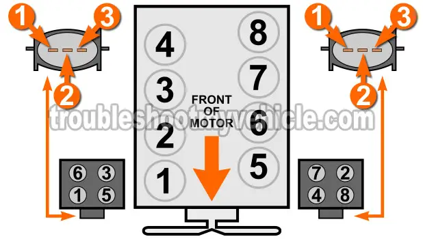
- Firing Order: 1-3-7-2-6-5-4-8
- Ignition System: Coil-on-Plug (COP)
Main Parts:
- Coil Packs: Each cylinder has its own individual coil pack directly mounted on the spark plug. This eliminates the need for a distributor and spark plug wires, improving ignition efficiency.
- Spark Plugs: Located within the cylinder head, they ignite the air-fuel mixture.
- Crankshaft Position Sensor (CKP): Provides the Engine Control Module (ECM) with information about the crankshaft's position and speed. This is vital for timing the ignition events.
- Camshaft Position Sensor (CMP): Provides the ECM with information about the camshaft's position, helping to identify which cylinder is in the firing position.
- Engine Control Module (ECM): The brain of the engine, controlling ignition timing, fuel injection, and other engine parameters based on sensor inputs.
Understanding the Coil Pack Diagram
The coil pack diagram is a visual representation of how the coil packs are wired and related to the cylinders. Let's break down the key elements:
Cylinder Numbering:
Ford V8 engines typically follow a standard cylinder numbering scheme. Facing the engine from the front of the vehicle:
- Right Bank (Passenger Side): Cylinders 1, 2, 3, and 4
- Left Bank (Driver Side): Cylinders 5, 6, 7, and 8
Coil Pack Placement:
In a Coil-on-Plug system, each coil pack sits directly atop its corresponding spark plug. The diagram will clearly show the location of each coil pack relative to the cylinder head and engine block.
Symbols and Conventions:
While specific diagrams can vary, look for these common elements:
- Lines: Lines represent wires connecting the coil packs to the ECM. Different colors might indicate different signals (e.g., power, ground, signal).
- Colors: Wire colors are standardized across the automotive industry. The diagram should include a key explaining what each color represents (e.g., Red = Battery Voltage, Black = Ground, etc.).
- Icons: Icons might represent specific components, such as connectors or sensors.
- Numbers: Cylinder numbers will be prominently displayed to show which coil pack corresponds to which cylinder.
How It Works
The 4.6L Ford F150 ignition system is a sophisticated electronic system. Here's a simplified explanation of how it works:
- The CKP and CMP sensors provide the ECM with real-time information about the engine's position and speed.
- The ECM calculates the precise moment to fire each spark plug based on factors like engine load, speed, and temperature.
- The ECM sends a low-voltage signal to the appropriate coil pack.
- The coil pack amplifies this low-voltage signal into a high-voltage surge (typically tens of thousands of volts).
- This high-voltage surge is sent to the spark plug, which creates a spark that ignites the air-fuel mixture within the cylinder.
The firing order (1-3-7-2-6-5-4-8) dictates the sequence in which the cylinders fire, ensuring smooth engine operation and optimal power delivery.
Real-World Use: Basic Troubleshooting
Let's consider a common scenario: your 4.6L F150 is experiencing a misfire. Here's how you can use the coil pack diagram to troubleshoot the issue:
- Identify the Misfiring Cylinder: Use an OBD-II scanner to retrieve diagnostic trouble codes (DTCs). The code will specify which cylinder is misfiring (e.g., P0301 indicates a misfire on cylinder 1).
- Locate the Corresponding Coil Pack: Refer to the coil pack diagram to identify the coil pack associated with the misfiring cylinder.
- Inspect the Coil Pack: Visually inspect the coil pack for any signs of damage, such as cracks, burns, or loose connectors.
- Swap the Coil Pack: Swap the coil pack with a known good coil pack from another cylinder. Clear the DTCs and restart the engine. If the misfire moves to the cylinder with the swapped coil pack, the original coil pack is likely the problem.
- Check the Wiring and Connectors: Inspect the wiring and connectors leading to the coil pack for any damage or corrosion. Use a multimeter to check for continuity and voltage at the connector.
If the misfire persists after these steps, the problem may lie with the spark plug, fuel injector, or other engine components. Further diagnostic testing may be required.
Safety Precautions
Working with the ignition system can be dangerous due to the high voltages involved. Observe the following safety precautions:
- Disconnect the Battery: Always disconnect the negative battery cable before working on the ignition system. This will prevent accidental shocks.
- Use Insulated Tools: Use insulated tools to prevent electrical shock.
- Avoid Contact with Live Wires: Never touch any exposed wires or connectors while the engine is running or the ignition system is energized.
- Be Aware of Residual Voltage: Even after the ignition is turned off, there may be residual voltage in the coil packs. Discharge the coil packs by grounding them before handling them.
- Proper Ventilation: Work in a well-ventilated area to avoid inhaling harmful fumes.
- High Energy Components: Coil packs are considered high energy components.