
Ford 1 Wire Alternator Wiring Diagram
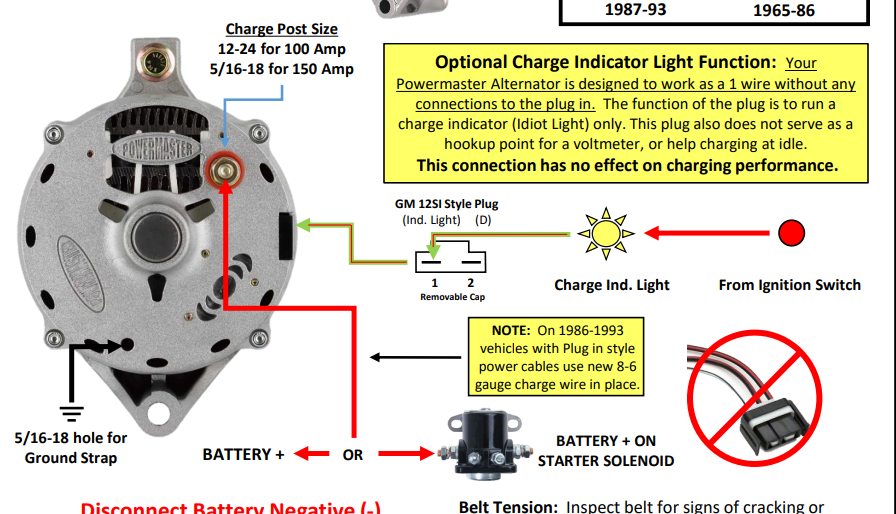
Alright, let's dive into the world of Ford 1-wire alternator wiring diagrams. Whether you're wrestling with a vintage Mustang, building a hot rod from the ground up, or just trying to diagnose a charging issue, understanding this system is crucial. This article will break down the diagram, explain how it works, and give you the knowledge you need to confidently tackle wiring it up.
Purpose and Importance
Why bother learning about this? Simple: Knowledge is power. With a firm grasp of the 1-wire alternator wiring diagram, you can:
- Troubleshoot charging system problems: Pinpoint faulty wiring or a failing alternator.
- Retrofit classic cars: Replace older, less reliable charging systems with a simpler, more efficient 1-wire setup.
- Build custom projects: Confidently wire up an alternator in a vehicle where the original wiring is non-existent or unsuitable.
- Gain a deeper understanding of automotive electrical systems: Expand your overall automotive expertise.
The beauty of a 1-wire alternator is its simplicity. Unlike traditional alternators requiring multiple wires for excitation and voltage sensing, the 1-wire unit only needs a single connection to the battery. This makes it ideal for simplified wiring harnesses and situations where minimal clutter is desired.
Key Specifications and Main Parts
Before we jump into the diagram itself, let's identify the key components and their specifications:
Main Parts
- 1-Wire Alternator: The heart of the system, responsible for generating electrical power.
- Battery: The energy storage device that provides power to start the engine and runs electrical components when the alternator isn't producing enough output. A 12V automotive battery is standard.
- Fuses or Fusible Links: Critical safety devices that protect the wiring and components from overcurrent conditions.
- Wiring Harness: The network of wires that connects the various components. Proper gauge wiring is critical!
- Ground Connection: A solid connection from the alternator housing and engine block to the chassis and battery negative terminal. Good grounding is essential for proper function.
Key Specs (Typical Values)
- Voltage Output: Typically 13.8-14.7 Volts DC (Direct Current). This is the ideal charging voltage for a 12V battery.
- Amperage Output: Varies depending on the alternator model, ranging from 60 amps to well over 100 amps. Choose an alternator with sufficient output for your vehicle's electrical needs.
- Wire Gauge: Use a wire gauge appropriate for the alternator's maximum amperage output. A general rule of thumb is to use at least 8-gauge wire for alternators up to 100 amps, and 4-gauge or larger for higher-output units. Check the alternator manufacturer's recommendations for specific requirements.
Understanding the Wiring Diagram Symbols
A wiring diagram is a roadmap for your electrical system. Here's a breakdown of common symbols you'll encounter:
- Solid Lines: Represent wires. The thickness of the line *may* indicate wire gauge, but often, you'll need to consult a separate wire size chart.
- Dashed Lines: Often represent ground connections or less critical wiring.
- Circles: Can represent various components, such as fuses, switches, or connectors. Look for labels or adjacent symbols to identify them.
- Rectangles: Often represent larger components like the alternator or battery.
- Battery Symbol: A series of alternating long and short lines. The long line represents the positive (+) terminal, and the short line represents the negative (-) terminal.
- Ground Symbol: A series of horizontal lines decreasing in size, typically connected to the chassis.
- Color Coding: Wires are often color-coded for easy identification. Common colors include red (power), black (ground), and other colors for various circuits. The diagram should include a color code key.
Keep in mind that wiring diagrams can vary slightly in their presentation, but the fundamental principles remain the same.
How a 1-Wire Alternator Works
Here's a simplified explanation of how a 1-wire alternator functions:
- Initial Excitation: When the engine starts, the alternator needs an initial "kick-start" to begin generating electricity. This is where the "1-wire" aspect comes in. Many 1-wire alternators are self-exciting, meaning they have an internal circuit that allows them to self-generate the initial voltage needed to start the charging process once the rotor spins fast enough. Some older 1-wire alternators might require a brief rev of the engine to initiate charging.
- Voltage Regulation: Once the alternator is generating power, an internal voltage regulator maintains a constant output voltage (typically around 14 volts) to charge the battery and power the vehicle's electrical system. The regulator automatically adjusts the alternator's output to compensate for changes in engine speed and electrical load.
- Charging the Battery: The alternator's output is directly connected to the positive terminal of the battery via a heavy-gauge wire. This connection allows the alternator to replenish the battery's charge as it's depleted by starting the engine and running electrical accessories.
- Grounding: The alternator must be properly grounded to the engine block and chassis. This provides a return path for the electrical current. A poor ground connection can lead to voltage drops, reduced charging performance, and even damage to the alternator.
The simplicity of the 1-wire system is its advantage, but it also means the alternator relies on its internal circuitry for excitation and regulation. In a traditional 3-wire alternator, the voltage regulator monitors the battery voltage directly and adjusts the alternator's output accordingly. A 1-wire alternator relies on sensing the voltage at its output terminal, which can be less accurate, especially if there are voltage drops in the wiring.
Real-World Use and Troubleshooting
Okay, let's get practical. Here are some common scenarios and troubleshooting tips:
- No Charging:
- Check the wiring: Ensure the wire from the alternator to the battery is securely connected and in good condition. Inspect for corrosion or damage.
- Verify ground connection: Make sure the alternator is properly grounded to the engine block and chassis. Clean any corroded ground connections.
- Test alternator output: Use a multimeter to measure the alternator's output voltage with the engine running. It should be between 13.8 and 14.7 volts. If it's significantly lower or zero, the alternator may be faulty.
- Battery Condition: A severely discharged or damaged battery can prevent the alternator from charging properly. Have the battery tested.
- Overcharging:
- Voltage Regulator: The internal voltage regulator is likely faulty. Replace the alternator.
- Erratic Charging:
- Wiring Issues: Loose connections, corroded terminals, or damaged wiring can cause erratic charging. Inspect the entire wiring circuit.
Safety Considerations
Working with automotive electrical systems can be dangerous. Here are some critical safety precautions:
- Disconnect the Battery: Always disconnect the negative terminal of the battery before working on any electrical components. This will prevent accidental shorts and potential electrical shocks.
- Use Proper Tools: Use insulated tools designed for automotive electrical work.
- Wear Safety Glasses: Protect your eyes from sparks and debris.
- Be Aware of High Current: Alternators can generate significant amounts of current, which can be dangerous if shorted. Avoid touching exposed wires or terminals while the engine is running.
- Fuses are your friend!: Always use properly rated fuses or fusible links in your wiring to protect the system from overcurrent conditions. Never bypass or replace a fuse with a higher-rated one.
Warning: The battery and the alternator are capable of delivering high currents. A short circuit can cause a fire, explosion, or serious injury. Exercise extreme caution when working on these components.
Mastering the 1-wire alternator wiring diagram opens up a world of possibilities for repairs, modifications, and custom builds. Remember to always prioritize safety, use quality components, and double-check your work. Good luck, and happy wiring!
We have a detailed, downloadable 1-Wire Alternator Wiring Diagram available for you. This diagram includes color-coded wiring, component labels, and helpful annotations. Download it now to further enhance your understanding and make your wiring project a breeze!