Ford 4 Wire O2 Sensor Wiring Diagram
Alright, let's dive into the world of Ford 4-wire Oxygen (O2) sensors. This article is your comprehensive guide to understanding the wiring diagram, its functionality, and how you can use this knowledge for diagnostics and repairs. Whether you're troubleshooting a persistent Check Engine Light, planning some modifications, or simply expanding your automotive knowledge, understanding the 4-wire O2 sensor wiring is a valuable skill. And just to let you know, we have a detailed wiring diagram available for download at the end of this article. It’ll be a handy reference as you work.
Why Understanding the Ford 4-Wire O2 Sensor Wiring Diagram Matters
Before we get into the nitty-gritty, let's address the 'why'. Knowing the wiring diagram of your Ford's 4-wire O2 sensor is crucial for several reasons:
- Accurate Diagnostics: A faulty O2 sensor can trigger a Check Engine Light (CEL) and negatively impact fuel efficiency and engine performance. The wiring diagram lets you pinpoint the problem, whether it's a broken wire, a bad connection, or a malfunctioning sensor.
- Safe Repairs: Working with electrical components requires caution. The wiring diagram helps you identify the correct wires for testing and repairs, minimizing the risk of accidental shorts or damage to the engine control unit (ECU).
- Modification and Upgrades: If you're planning any modifications to your exhaust system or engine management, understanding the O2 sensor wiring is essential for proper integration and preventing unforeseen issues.
- Learning Automotive Electrical Systems: The O2 sensor is a relatively simple, yet vital, component in modern engines. Understanding its wiring is a stepping stone to grasping more complex automotive electrical systems.
Key Specs and Main Parts of a 4-Wire O2 Sensor
Let's break down the basics. The 4-wire O2 sensor, unlike its 1, 2, or 3-wire counterparts, incorporates a dedicated heater circuit. This heater is key to its performance. The main components are:
- Zirconium Dioxide (ZrO2) or Titania (TiO2) Sensing Element: This is the heart of the sensor. It's a ceramic element that generates a voltage signal based on the difference in oxygen concentration between the exhaust gas and the surrounding atmosphere. Zirconium dioxide sensors are the most common type in Ford vehicles.
- Heater Element: The heater is a resistance coil that heats the sensing element to its optimal operating temperature (around 600°F or 315°C) quickly. This is particularly important during cold starts when the exhaust gas isn't hot enough to activate the sensor.
- Signal Wire: This wire carries the voltage signal from the sensing element to the ECU. The voltage varies depending on the oxygen content in the exhaust. A low voltage (near 0.1V) indicates lean conditions (high oxygen), while a high voltage (near 0.9V) indicates rich conditions (low oxygen).
- Ground Wire: Provides a ground reference for the signal.
- Heater Power Wire: Supplies power to the heater element, typically 12V.
- Heater Ground Wire: Provides a ground path for the heater circuit.
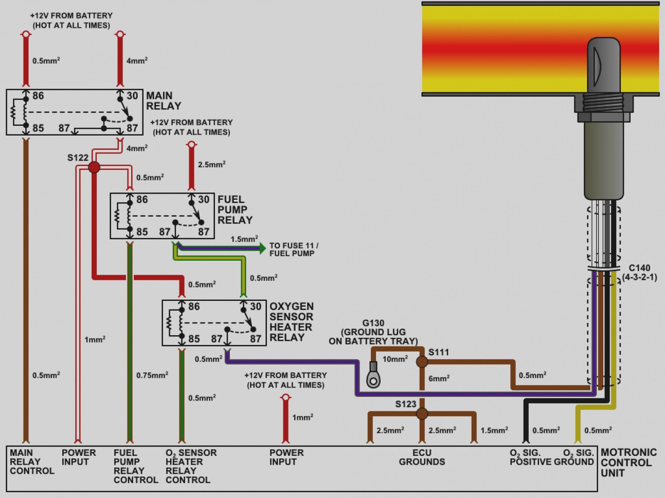
Decoding the Symbols: Lines, Colors, and Icons
A typical Ford 4-wire O2 sensor wiring diagram will use various symbols to represent components and connections. Let's decipher them:
- Solid Lines: Represent wires. Thicker lines usually indicate power wires, while thinner lines are typically signal or ground wires.
- Dashed Lines: May represent shielded wires or connections to other components.
- Color Codes: Wire colors are crucial for identification. Ford uses a variety of color codes, and these can change between models and years. The wiring diagram will provide a key that explains each color. For example, a common configuration might have:
- White: Heater Power
- White: Heater Ground
- Black: Signal Wire
- Gray: Signal Ground
- Ground Symbol (
 ): Indicates a connection to ground.
 - Component Symbols: The O2 sensor itself is typically represented by a stylized drawing or a rectangle with pins indicating the wire connections. The heater may be shown as a resistor symbol.
- Connector Symbols: Connectors are usually depicted as squares or rectangles with numbers indicating the pin numbers.
How It Works: A Step-by-Step Explanation
Here's how the 4-wire O2 sensor system functions:
- Cold Start: When the engine is cold, the ECU sends power to the heater element through the heater power wire. The heater rapidly heats the sensing element.
- Oxygen Sensing: As the sensing element reaches its operating temperature, it begins to measure the oxygen content in the exhaust gas. The difference in oxygen levels creates a voltage potential.
- Signal Generation: The voltage signal generated by the sensing element is transmitted to the ECU via the signal wire. The signal voltage is referenced to ground through the signal ground wire.
- ECU Interpretation: The ECU reads the voltage signal from the O2 sensor. It uses this information to adjust the air-fuel ratio. If the signal indicates a lean condition, the ECU will richen the mixture by increasing fuel injection. If the signal indicates a rich condition, the ECU will lean the mixture by decreasing fuel injection.
- Closed-Loop Operation: This feedback loop between the O2 sensor and the ECU is called closed-loop operation. It allows the engine to maintain optimal air-fuel ratio for efficient combustion and reduced emissions.
Real-World Use: Basic Troubleshooting Tips
Now, let's put this knowledge to practical use. Here are a few troubleshooting tips using the wiring diagram:
- Check for Voltage: Use a multimeter to check for voltage at the heater power wire when the engine is cold and the ignition is on. You should see approximately 12V. If not, check the fuse and wiring leading to the sensor.
- Check Resistance: Disconnect the sensor and use a multimeter to measure the resistance across the heater power and ground pins. A typical resistance value is between 5 and 20 ohms. An open circuit (infinite resistance) indicates a faulty heater.
- Check Signal Wire Voltage: With the engine running and warmed up, use a multimeter to measure the voltage at the signal wire. It should fluctuate between approximately 0.1V and 0.9V, indicating that the sensor is responding to changes in exhaust gas oxygen content. A steady voltage suggests a potential sensor failure or wiring issue.
- Inspect Wiring: Carefully inspect the wiring harness for any signs of damage, such as frayed wires, broken connectors, or corrosion. Use the wiring diagram to trace the wires back to their source and identify any potential problem areas.
- Check the Ground Connections: Ensure that the ground wires are securely connected to the chassis or engine block. A loose or corroded ground connection can cause erratic sensor readings.
Safety First: Handling O2 Sensors and Electrical Components
Working with automotive electrical systems requires caution. Keep these safety tips in mind:
- Disconnect the Battery: Before working on any electrical components, disconnect the negative battery terminal to prevent accidental shorts.
- Wear Safety Glasses: Protect your eyes from debris and sparks.
- Use Proper Tools: Use insulated tools specifically designed for automotive electrical work.
- Be Careful with Heat: The exhaust system gets extremely hot. Allow the engine to cool completely before working on the O2 sensor.
- Don't Over-Tighten: When reinstalling the O2 sensor, don't over-tighten it. Follow the manufacturer's torque specifications.
- Be Aware of the ECU: The ECU is a sensitive electronic device. Avoid static electricity and handle it with care. Never disconnect or connect components while the ignition is on.
Working on your car can be rewarding, but safety should always be your top priority. If you're not comfortable with electrical work, it's best to consult a qualified mechanic.
By understanding the Ford 4-wire O2 sensor wiring diagram, you can diagnose problems, perform repairs, and even plan modifications with confidence.
Download Your Ford 4-Wire O2 Sensor Wiring Diagram
As promised, we have compiled a generic 4-wire O2 sensor wiring diagram that will help in your projects. This diagram is a great starting point, however, be sure to consult the exact wiring diagram that is specific to the year, make, and model of your vehicle.
We have that file right here, ready for you to download and use as a reference guide for your vehicle. Simply click the link to download your copy. Now, get out there and put your newfound knowledge to good use!