
Ford 5 Wire Wiper Motor Wiring Diagram
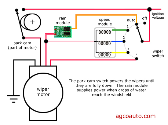
Let's dive deep into the fascinating world of Ford 5-wire wiper motor wiring diagrams. If you're an intermediate car owner, a seasoned modder, or a DIY mechanic, understanding this diagram is crucial for diagnosing wiper issues, performing repairs, or even customizing your vehicle's electrical system. It’s more than just a schematic; it’s a roadmap to functionality.
Purpose of Understanding the Ford 5-Wire Wiper Motor Wiring Diagram
Why bother with a wiring diagram? The answer is simple: control. Armed with a clear understanding, you can:
- Troubleshoot Wiper Problems: Diagnose issues like intermittent operation, no operation, or wipers that won't turn off.
- Perform Repairs: Replace a faulty motor, switch, or wiring harness with confidence.
- Customize Your Electrical System: Add aftermarket accessories or modify the wiper system for specific needs (e.g., intermittent wiping control upgrade).
- Understand Basic Automotive Electrics: Reinforce your understanding of automotive electrical circuits in general.
Key Specs and Main Parts
Before we dissect the diagram, let's get familiar with the key components:
- Wiper Motor: The heart of the system, converting electrical energy into mechanical motion to move the wiper arms. The 5 wires give it enhanced control and parking functionality.
- Wiper Switch: Usually located on the steering column, this switch controls the wiper motor's speed (low, high, intermittent) and On/Off state.
- Wiring Harness: A bundle of wires that connect the wiper motor, switch, and other components, like the grounding point and power source.
- Fuse: A safety device that protects the circuit from overloads.
- Ground Connection: Provides a return path for the electrical current, essential for completing the circuit.
The "5-wire" designation is crucial. These wires typically control the following:
- Power (High Speed): Direct power for the high-speed setting.
- Power (Low Speed): Direct power for the low-speed setting.
- Park Switch Signal: Informs the motor when the wipers are in the "parked" position. This is critical for the automatic parking function.
- Power (Ignition Switched): Often a fused connection that only supplies power when the ignition is on.
- Ground: Provides the return path for current flow.
Deciphering the Symbols: Lines, Colors, and Icons
A wiring diagram is a symbolic language. Let's decode it:
- Lines: Represent wires. The thickness of the line doesn't usually indicate wire gauge, but rather helps visually distinguish the wires.
- Colors: Each wire has a specific color. The diagram will include a key explaining which color corresponds to which function (e.g., Red = Battery Power, Black = Ground). Matching colors is *critical* when troubleshooting or wiring.
- Icons:
- Motor Symbol: A stylized representation of the wiper motor.
- Switch Symbol: Indicates the wiper switch, often showing multiple positions (Off, Low, High, Intermittent).
- Fuse Symbol: A zigzag line inside a rectangle.
- Ground Symbol: Usually three downward-pointing lines.
- Connector Symbol: Indicates a point where wires connect via a plug.
- Numbers/Letters: Terminals on the motor and switch are usually labeled with numbers or letters. The diagram shows which wire connects to which terminal.
Understanding wire color codes is especially important. Standard automotive wiring uses specific colors to denote different circuits. While Ford's color codes may vary slightly by year and model, certain colors are generally consistent (e.g., black for ground). The legend on the diagram is your bible.
How It Works: A Step-by-Step Explanation
The basic operation is as follows:
- Power Supply: Power from the battery (often ignition-switched) flows through the fuse to the wiper switch.
- Switch Selection: The driver selects a wiper speed (Off, Low, High, Intermittent) on the switch.
- Circuit Activation: The selected position on the switch closes the appropriate circuit, sending power to the corresponding wire(s) on the wiper motor.
- Motor Operation: The motor converts the electrical energy into mechanical motion, turning the wiper arms.
- Park Function: When the wiper switch is turned to the "Off" position, the park switch circuit is activated. This circuit allows the motor to complete its current cycle and park the wipers in the correct position (usually at the bottom of the windshield). This is achieved with an internal switch within the motor assembly itself.
- Ground: The electrical circuit is completed through the ground wire connected to the vehicle's chassis.
The park function is a key element of the 5-wire system. The park switch sends a signal to the motor to continue running until the wipers reach their resting position. This ensures that the wipers always stop at the bottom of the windshield, not mid-sweep.
Real-World Use: Basic Troubleshooting Tips
Here are some common problems and how to diagnose them using the wiring diagram:
- Wipers Don't Work at All:
- Check the fuse. A blown fuse is the most common culprit.
- Verify power to the wiper switch using a multimeter.
- Check the ground connection. Ensure it's clean and secure.
- Test the wiper motor directly by applying 12V to the power wires. If it doesn't run, the motor is likely faulty.
- Wipers Only Work on High Speed:
- The low-speed circuit may be faulty. Trace the low-speed wire from the switch to the motor, checking for breaks or shorts.
- The low-speed winding within the motor may be damaged.
- Wipers Won't Turn Off:
- The wiper switch may be faulty.
- The park switch inside the motor may be stuck or damaged.
- Wipers Don't Park Correctly:
- The park switch circuit may be faulty. Check the wiring and the park switch inside the motor.
When troubleshooting, always use a multimeter to check for voltage and continuity. A multimeter is your best friend in electrical diagnostics.
Safety Considerations
Working with automotive electrical systems can be dangerous. Here are some safety precautions:
- Disconnect the Battery: Before working on any electrical circuit, disconnect the negative terminal of the battery to prevent accidental shorts.
- Work in a Well-Ventilated Area: Batteries can produce explosive gases.
- Use Proper Tools: Use insulated tools to avoid electric shock.
- Avoid Water: Never work on electrical systems in wet conditions.
- Be Careful with Wiring: Damaged or frayed wiring can cause shorts and fires. Replace any damaged wiring immediately.
Capacitors, sometimes present in more complex wiper motor control modules, can store a charge even after the battery is disconnected. Be careful when handling these components. They can deliver a shock. If you are uncomfortable with any task, seek professional help.
Understanding the Ford 5-wire wiper motor wiring diagram empowers you to diagnose and repair wiper system issues effectively. Remember to take your time, follow the diagram carefully, and prioritize safety. Good luck with your project!
We have the Ford 5-wire wiper motor wiring diagram file available for download. It will be invaluable for your troubleshooting and repair efforts.