
Ford 5.4 Brake Booster Vacuum Line Diagram
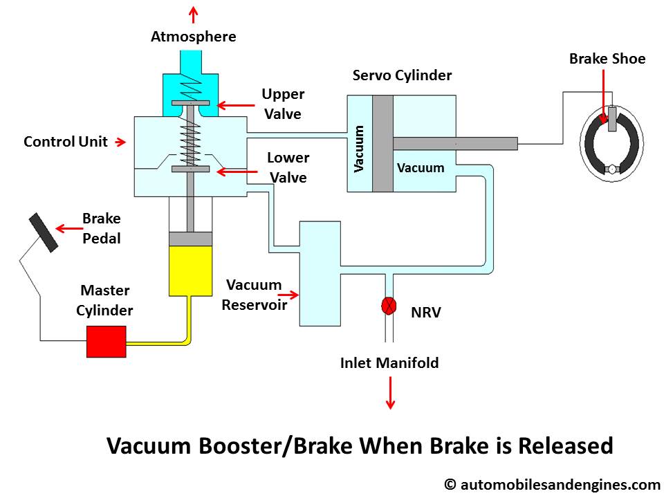
Alright, let's dive into the vacuum line diagram for the Ford 5.4L brake booster. This is crucial information whether you're tackling a brake issue, chasing down a vacuum leak, or just deepening your understanding of your vehicle's systems. This article will serve as a comprehensive guide, explaining everything from the diagram's purpose to troubleshooting tips. And remember, we've got a downloadable diagram ready for you at the end of this article. Let's get started!
Purpose of the Brake Booster Vacuum Line Diagram
Why bother with a diagram? Several reasons. Firstly, it's indispensable for repairs. If you're replacing a cracked or damaged vacuum line, the diagram shows you exactly where it connects. Secondly, it's a powerful tool for diagnostics. A vacuum leak in the brake booster system can lead to a hard brake pedal, poor engine performance, and even trigger the Check Engine Light. The diagram helps you systematically trace the vacuum lines to pinpoint the source of the leak. Finally, it's great for learning. Understanding how the brake booster system works will allow you to perform your own preventative maintenance and ensure your Ford 5.4L braking system is working optimally.
Key Specs and Main Parts
Before we get to the diagram itself, let’s cover the essential components of the brake booster system on a Ford 5.4L engine. Here's a breakdown of the main parts involved:
- Brake Booster (Servo): The primary component that multiplies the force you apply to the brake pedal. It uses engine vacuum to assist in pressing the master cylinder piston, making it easier to stop the vehicle.
- Master Cylinder: Located directly behind the brake booster. It contains brake fluid and is responsible for sending hydraulic pressure to the brake calipers/wheel cylinders when you press the brake pedal.
- Vacuum Hose: A reinforced rubber hose that connects the brake booster to a vacuum source on the engine, typically the intake manifold. This hose must be in good condition to maintain proper vacuum.
- Check Valve: A one-way valve installed in the vacuum hose, usually near the brake booster. It allows vacuum to be drawn from the booster but prevents it from escaping. This is critical in case the engine vacuum suddenly drops (e.g., during hard acceleration). The check valve ensures you have at least one assisted brake application.
- Intake Manifold Vacuum Port: The source of vacuum. This port is usually located on the intake manifold and is connected to the vacuum hose leading to the brake booster.
Key Specs: The vacuum level in the intake manifold is typically around 17-22 inches of mercury (inHg) at idle. This is a crucial parameter for proper brake booster operation. A vacuum gauge can be used to verify this value.
Understanding the Vacuum Line Diagram Symbols
A diagram is only useful if you know how to interpret it. Here’s a breakdown of common symbols you might encounter:
- Solid Lines: Generally represent vacuum hoses. Thicker lines may indicate larger diameter hoses.
- Dotted Lines: Can indicate control signals, wiring, or less critical vacuum lines (e.g., those for emission control systems – which are often connected to the same vacuum source).
- Arrows: Show the direction of vacuum flow.
- Specific Icons: Icons will depict the components we listed above such as the brake booster, check valve, and intake manifold. The diagram we have available uses standardized automotive symbols for these parts.
- Color Coding: Some diagrams use color coding to differentiate vacuum lines based on function (e.g., a specific color for brake booster vacuum, another for EGR control, etc.). Check the diagram's legend for specific color meanings.
Carefully inspect the legend of the diagram you are using to ensure correct interpretation of all symbols and line types.
How the Brake Booster System Works
The brake booster is a clever device that uses engine vacuum to amplify the force you apply to the brake pedal. Here’s a simplified explanation of how it works:
- Engine Vacuum: The engine creates a vacuum in the intake manifold. This vacuum is connected to one side of the brake booster's internal diaphragm.
- Brake Pedal Input: When you press the brake pedal, a valve inside the booster opens, allowing atmospheric pressure (outside air) to enter the other side of the diaphragm.
- Pressure Differential: This creates a pressure difference across the diaphragm – vacuum on one side, atmospheric pressure on the other. This pressure difference assists in pushing the master cylinder piston.
- Assisted Braking: The combined force of your foot and the vacuum assist provides significantly more braking power than your foot alone.
The check valve is there to maintain vacuum within the booster, even if the engine vacuum fluctuates. This provides you with power-assisted braking for at least one application if the engine stalls or vacuum is lost.
Real-World Use: Basic Troubleshooting Tips
Let's look at some common problems and how the diagram helps diagnose them:
- Hard Brake Pedal: This is the classic symptom of a brake booster problem. Use the diagram to check the vacuum hose for cracks, kinks, or disconnections. Also, test the check valve to ensure it's functioning correctly. A vacuum gauge connected to the booster hose can also confirm sufficient vacuum.
- Poor Engine Performance (Rough Idle, Hesitation): A vacuum leak in the brake booster system can affect the engine's air-fuel ratio, leading to poor performance. The diagram helps you isolate the brake booster circuit from other vacuum lines, making it easier to identify the leak source. Spraying brake cleaner or starting fluid around the hose connections while the engine is running can help locate a leak (listen for a change in engine RPM).
- Hissing Sound: A hissing sound near the brake booster or vacuum lines is often a telltale sign of a vacuum leak. Use the diagram to trace the lines and identify the source of the hiss.
- Check Engine Light (CEL): A vacuum leak can trigger various CEL codes related to fuel trim or manifold pressure. While the CEL doesn't directly indicate a brake booster problem, using the diagram alongside the code description can help narrow down the potential causes.
Safety Considerations
When working on the brake booster system, safety is paramount. Here are a few key points:
- Brake Fluid: Brake fluid is corrosive and can damage painted surfaces. Handle it with care and wear appropriate eye protection.
- Vacuum Leaks: When searching for vacuum leaks using flammable sprays (brake cleaner, starting fluid), be extremely cautious around hot engine components. Ensure proper ventilation and have a fire extinguisher nearby.
- Brake Pedal Test: After making any repairs to the brake booster system, perform a brake pedal test before driving the vehicle. Start the engine and ensure the brake pedal feels firm and responsive. If the pedal feels spongy or goes to the floor, there may be air in the brake lines or other issues that need to be addressed immediately.
- Check Valve Orientation: Ensure the check valve is installed correctly, according to the diagram. Incorrect installation will prevent the booster from functioning properly.
Working on the brake system requires careful attention to detail and a thorough understanding of the system's operation. If you are unsure about any aspect of the repair, it's always best to consult with a qualified mechanic.
We hope this guide has provided you with a solid understanding of the Ford 5.4L brake booster vacuum line diagram. Now that you've got the knowledge, remember that we have the detailed diagram ready for you to download. This diagram provides a visual representation of the vacuum lines, components, and their connections, making troubleshooting and repairs much easier.