Ford 6.0 6.0 Powerstroke Cooling System Diagram
The Ford 6.0L Powerstroke diesel engine, found in Ford trucks and vans from 2003 to 2007, is a powerful but sometimes temperamental workhorse. One of its known weak points is the cooling system. Understanding the cooling system diagram is absolutely essential for diagnosing overheating issues, performing repairs, or even making modifications. Think of it as your roadmap for keeping your 6.0L running cool and efficiently. We have a high-resolution version of the cooling system diagram available for download at the end of this article. Let's dive in.
Why This Diagram Matters
Having a clear understanding of the 6.0L Powerstroke cooling system is crucial for several reasons:
- Troubleshooting Overheating: The 6.0L is notorious for overheating problems. The diagram allows you to systematically trace coolant flow and identify potential blockages or failures.
- Performing Repairs: Whether you're replacing a water pump, thermostat, or EGR cooler, the diagram guides you through the component locations and connections.
- Making Modifications: Upgrading the cooling system with aftermarket parts (e.g., a larger radiator or upgraded coolant filter) requires a solid understanding of the stock system's layout.
- Preventative Maintenance: By understanding the system, you can better identify potential weak points and perform preventative maintenance to avoid costly repairs down the road.
- Learning the System: Simply put, knowing how the cooling system works empowers you to make informed decisions about your truck and its maintenance.
Key Specs and Main Parts
Before we get into the diagram itself, let's review the key components of the 6.0L Powerstroke cooling system:
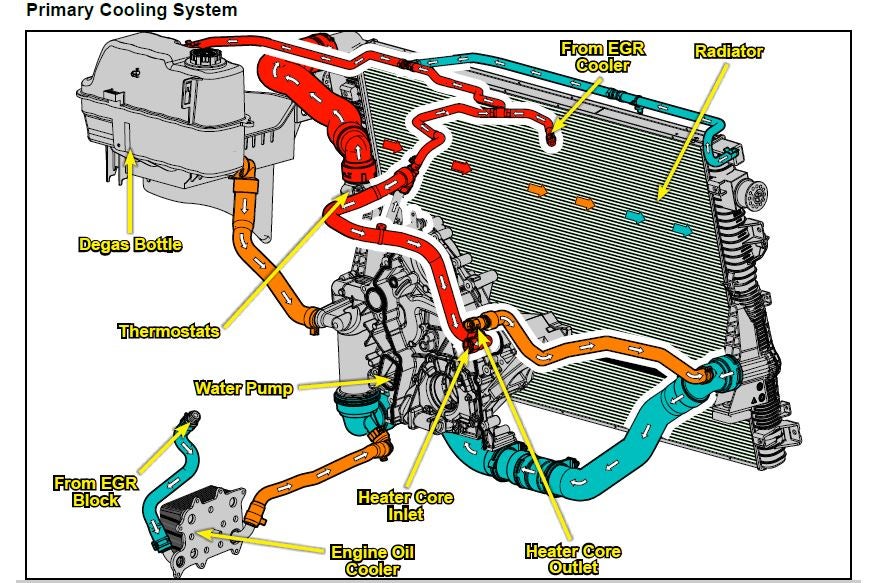
- Radiator: The primary heat exchanger, responsible for dissipating heat from the coolant to the atmosphere. Look for telltale signs of leaks or damage here.
- Water Pump: Circulates coolant throughout the engine and cooling system. Critical for maintaining flow.
- Thermostat: Regulates engine temperature by controlling coolant flow to the radiator. A stuck-closed thermostat is a common cause of overheating.
- EGR Cooler: Cools exhaust gases before they are recirculated into the intake. A common failure point on the 6.0L, often leaking internally and causing coolant loss. A notorious troublemaker!
- Oil Cooler: Cools engine oil, which also contributes significantly to the overall heat load. Prone to clogging and leaking, leading to oil cooler failure.
- Coolant Reservoir (Degas Bottle): Provides a space for coolant expansion and contraction and allows for air to be purged from the system. The cap's pressure rating is important.
- Coolant Hoses: Carry coolant between the various components. Check for cracks, leaks, and bulges.
- Coolant Fan Clutch: Engages the cooling fan to increase airflow through the radiator when needed.
- Coolant Temperature Sensor (ECT): Monitors coolant temperature and sends data to the engine control module (ECM).
Key Specs to Keep in Mind:
- Coolant Type: Use a coolant compatible with diesel engines, typically a Heavy Duty Extended Life Coolant (HD ELC) that meets Ford specification WSS-M97B44-D. Using the wrong coolant can lead to corrosion and cavitation.
- System Capacity: The 6.0L Powerstroke cooling system typically holds around 24-26 quarts of coolant, depending on the specific configuration (e.g., with or without rear heat).
- Thermostat Temperature: The stock thermostat is typically rated for 192-195 degrees Fahrenheit.
- Coolant Pressure Cap: The coolant reservoir cap is designed to maintain a specific pressure (typically around 16 psi). A faulty cap can lead to coolant loss.
Understanding the Diagram Symbols
A cooling system diagram uses various symbols to represent different components and flow paths. Here's a breakdown of common symbols you'll encounter:
- Solid Lines: Typically represent coolant hoses or pipes carrying liquid coolant.
- Dotted Lines: May represent vacuum lines or small-diameter hoses used for overflow or venting.
- Arrows: Indicate the direction of coolant flow. Pay close attention to these!
- Rectangles: Often represent heat exchangers like the radiator, EGR cooler, or oil cooler.
- Circles: Can represent sensors, valves, or smaller components.
- Specific Colors: Sometimes, diagrams use different colors to distinguish between hot and cold coolant lines, or to differentiate between different sections of the system (e.g., the EGR cooling loop).
- Component Labels: The diagram will label each component with its name or abbreviation (e.g., "Radiator," "Water Pump," "EGR Cooler").
Understanding these symbols will allow you to quickly interpret the diagram and trace coolant flow through the system.
How It Works: Coolant Flow
The 6.0L Powerstroke cooling system operates on a closed-loop principle. Here's a simplified explanation of the coolant flow:
- The water pump draws coolant from the bottom of the radiator.
- The coolant is then pumped through the engine block and cylinder heads, absorbing heat generated by combustion.
- From the engine, some coolant flows to the oil cooler to help regulate oil temperature.
- Another portion of coolant is routed to the EGR cooler, where it cools the hot exhaust gases being recirculated.
- The coolant then passes through the thermostat housing. If the engine is cold, the thermostat remains closed, and the coolant is recirculated back to the water pump. This allows the engine to warm up quickly.
- Once the engine reaches its operating temperature, the thermostat opens, allowing coolant to flow to the radiator.
- As the coolant passes through the radiator, heat is dissipated to the atmosphere.
- The cooled coolant then returns to the water pump, completing the cycle.
- The coolant reservoir acts as an expansion tank, accommodating changes in coolant volume due to temperature fluctuations. It also allows for air to be purged from the system.
Understanding this flow path is essential for troubleshooting cooling system problems. For instance, if you suspect a blockage, you can use the diagram to trace the coolant flow and pinpoint the potential location of the obstruction.
Real-World Use: Basic Troubleshooting Tips
Here are some basic troubleshooting tips using the cooling system diagram:
- Overheating:
- Check the coolant level in the reservoir. Low coolant is a common cause of overheating.
- Inspect the radiator for obstructions (e.g., debris, bugs).
- Verify that the cooling fan is engaging properly.
- Check the thermostat for proper operation. A stuck-closed thermostat will prevent coolant from flowing to the radiator.
- Look for leaks at hoses, connections, and components (especially the EGR cooler).
- Coolant Loss:
- Inspect all hoses and connections for leaks.
- Check the water pump for leaks around the weep hole.
- Examine the EGR cooler for signs of internal leaks (coolant smell in the exhaust, white smoke).
- Look for leaks around the oil cooler housing.
- White Smoke (Especially on Startup):
- This is often a sign of coolant entering the combustion chambers, typically due to a leaking EGR cooler or head gasket.
Remember: Always start with the simplest checks first, such as coolant level and hose condition, before moving on to more complex diagnostics.
Safety Considerations
Working on the cooling system involves certain safety risks:
- Hot Coolant: Never open the coolant reservoir cap when the engine is hot. The system is pressurized, and hot coolant can spray out, causing severe burns. Let the engine cool down completely before opening the cap.
- Rotating Parts: Keep hands and tools away from the cooling fan when the engine is running.
- High Pressure: The cooling system operates under pressure. Relieve the pressure before disconnecting hoses or components.
- Chemical Exposure: Coolant is toxic. Avoid contact with skin and eyes, and dispose of used coolant properly.
- EGR Cooler: Be especially careful when working around the EGR cooler, as it can be extremely hot.
Always wear safety glasses and gloves when working on the cooling system.
By understanding the cooling system diagram and following proper safety procedures, you can confidently diagnose and repair cooling system issues on your Ford 6.0L Powerstroke.
Download the Diagram
For a high-resolution version of the 6.0L Powerstroke cooling system diagram, you can download it here. Having a detailed diagram readily available will be invaluable when working on your truck.