Ford Alternator Wiring Diagram Internal Regulator
Understanding the Ford alternator wiring diagram, specifically for models with an internal regulator, is crucial for a variety of reasons. Whether you're tackling a no-start condition, experiencing dim headlights, or simply want to upgrade your charging system, knowing how the alternator interacts with the rest of the electrical system can save you time, money, and frustration. This guide will break down the diagram, its components, and its function, offering practical advice for diagnosis and repair.
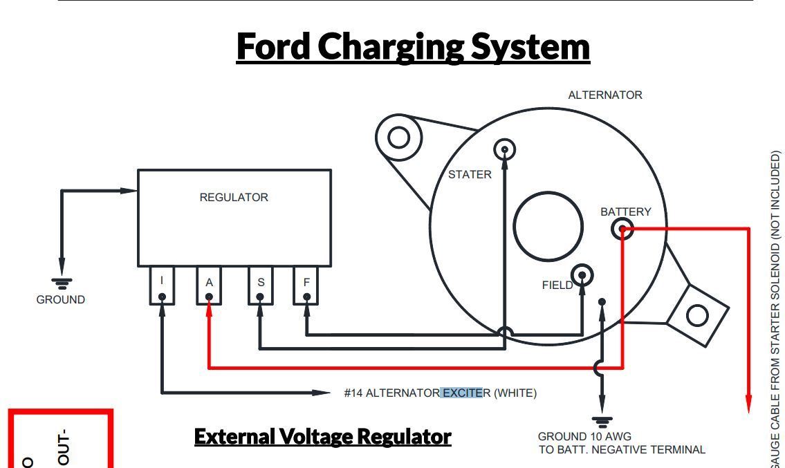
Purpose of the Alternator Wiring Diagram
The alternator wiring diagram serves as a roadmap for the electrical connections of your Ford's charging system. It outlines the pathways for current flow between the alternator, battery, voltage regulator (internal in this case), and other relevant components. Understanding this diagram allows you to:
- Diagnose Charging Issues: Pinpoint shorts, opens, or voltage drops that prevent the alternator from properly charging the battery.
- Perform Repairs: Correctly reconnect wires after repairs or modifications, ensuring proper circuit function.
- Understand System Function: Gain a deeper understanding of how the charging system works, allowing for more informed troubleshooting and upgrades.
- Customization/Upgrades: Properly integrate higher-output alternators or perform wiring modifications for specific needs (e.g., adding auxiliary batteries).
Key Specs and Main Parts
Let's define some key terms and components before we dive into the wiring details:
- Alternator: The primary device responsible for generating electricity to charge the battery and power the vehicle's electrical systems while the engine is running. It converts mechanical energy from the engine into electrical energy.
- Internal Regulator: A solid-state electronic device integrated inside the alternator that regulates the output voltage. This prevents overcharging the battery, which can damage it and other components. Ford moved to internal regulators in the late 1960s/early 1970s.
- Battery: Stores electrical energy to start the engine and provide power when the alternator's output is insufficient (e.g., at idle with heavy electrical loads).
- Battery Positive Terminal (B+): The main output terminal of the alternator, typically a large-gauge wire connected directly to the positive terminal of the battery (often through a fusible link or megafuse).
- Stator: The stationary part of the alternator containing the windings where electricity is induced.
- Rotor: The rotating part of the alternator, containing a field winding energized by the regulator.
- Rectifier (Diode Bridge): Converts the AC voltage produced by the stator into DC voltage needed by the vehicle's electrical system.
- Ignition (IGN) or "I" Terminal: A wire connected to the ignition circuit. When the ignition switch is turned on, this provides a small voltage signal to the regulator, "exciting" it and allowing the alternator to start charging.
- Voltage Sense (S) Terminal: This wire monitors the battery voltage and provides feedback to the internal regulator. This allows the regulator to adjust the alternator's output to maintain a consistent charging voltage. Some alternators may not have this separate terminal, relying instead on the B+ voltage at the alternator.
- Ground: A critical connection providing a return path for current flow. Typically connected to the engine block or chassis.
- Fusible Link/Megafuse: A safety device designed to protect the wiring and components from overcurrent. It's a wire designed to melt and break the circuit if the current exceeds a certain level.
Symbols - Lines, Colors, and Icons
Understanding the symbols used in the wiring diagram is essential for proper interpretation.
- Lines: Represent wires. Thicker lines usually indicate heavier-gauge wires capable of carrying more current.
- Colors: Used to differentiate wires and circuits. Ford often uses color codes like Red for battery positive, Black for ground, and other colors for specific circuits (e.g., Yellow/White for ignition). Always refer to the specific diagram for the correct color code for your vehicle.
- Icons: Represent components. Standard symbols are used for resistors, capacitors, diodes, and other electronic parts. The alternator itself is usually represented by a circle with the letter "G" inside (for generator).
- Numbers: Indicate wire gauge (e.g., 10 AWG, 12 AWG). Lower numbers represent thicker wires.
- Ground Symbol: Usually three horizontal lines stacked on top of each other, tapering towards the bottom.
Wire Gauge: This is especially important. Using a wire that is too thin can lead to overheating and even fire.
How It Works
Here's a simplified explanation of how the Ford alternator with an internal regulator functions:
- Ignition Excitation: When the ignition key is turned to the "ON" position, a small voltage (typically 12V) is applied to the ignition (IGN or "I") terminal of the alternator. This signal activates the internal regulator.
- Field Current: The regulator controls the amount of current flowing through the rotor's field winding. This current creates a magnetic field.
- Voltage Generation: As the rotor spins inside the stator, its magnetic field induces an AC voltage in the stator windings.
- Rectification: The rectifier (diode bridge) converts the AC voltage from the stator into DC voltage.
- Voltage Regulation: The internal regulator monitors the output voltage (via the voltage sense terminal, if present, or the B+ terminal) and adjusts the field current to maintain a consistent charging voltage (typically around 13.8V to 14.4V). If the battery voltage is low, the regulator increases the field current to increase the alternator's output. If the battery voltage is high, the regulator decreases the field current.
- Battery Charging: The regulated DC voltage from the alternator is then fed to the battery through the B+ terminal, charging the battery and powering the vehicle's electrical systems.
Real-World Use - Basic Troubleshooting Tips
Here are some common issues you might encounter and how to troubleshoot them using the wiring diagram:
- No Charging (Battery Light On): Use a multimeter to check for voltage at the B+ terminal of the alternator with the engine running. If there's no voltage, check the fusible link/megafuse and the wiring between the alternator and the battery. Also, verify that the ignition wire is receiving voltage when the ignition is on. A faulty regulator or alternator itself is also possible.
- Overcharging (Battery Boiling): This often indicates a faulty internal regulator. Use a multimeter to monitor the battery voltage with the engine running. If the voltage exceeds 14.8V, the regulator is likely the problem.
- Dim Headlights/Flickering Lights: Could be due to low alternator output. Check the alternator's output voltage under load (e.g., with headlights and accessories on). Also, inspect the ground connections for corrosion or looseness. Poor ground connections can cause significant voltage drops.
- Excessive Voltage Drop: Use a multimeter to measure voltage drops across various points in the circuit (e.g., between the alternator output and the battery positive terminal). Excessive voltage drops indicate resistance in the wiring, which can be caused by corroded connections, damaged wires, or undersized wiring.
Safety – Highlight Risky Components
Working with automotive electrical systems can be dangerous. Here are some safety precautions:
- Disconnect the Battery: Always disconnect the negative battery cable before working on the electrical system. This prevents accidental shorts and electrical shocks.
- High Current: The alternator and battery cables carry high currents. Be careful not to short them to ground.
- Moving Parts: Be extremely cautious around the engine and alternator while the engine is running. Keep hands, clothing, and tools away from moving parts.
- Fusible Links/Megafuses: Always replace fusible links/megafuses with the correct amperage rating. Using a higher-rated fuse can allow excessive current to flow, potentially causing a fire.
This guide provides a solid foundation for understanding the Ford alternator wiring diagram with an internal regulator. Remember to always consult the specific wiring diagram for your vehicle's year and model, as there may be variations. With a little patience and careful troubleshooting, you can confidently diagnose and repair your charging system.
For detailed Ford alternator wiring diagrams and further technical information, you can access relevant files to assist you with repairs or educational purposes.