Ford Bronco Starter Solenoid Wiring Diagram
Understanding the Ford Bronco's starter solenoid wiring diagram is essential for any serious DIY mechanic, modder, or owner who wants to tackle electrical repairs and upgrades with confidence. Whether you're dealing with a no-start condition, planning an engine swap, or simply wanting to deepen your understanding of your Bronco's electrical system, this diagram is your roadmap. Having the diagram available allows for targeted troubleshooting, prevents costly misdiagnoses, and empowers you to perform repairs correctly.
Why You Need to Understand the Starter Solenoid Wiring Diagram
The starter solenoid is a critical component in the starting circuit. It acts as both a high-current switch and a relay, allowing the relatively low current from the ignition switch to control the high current needed to engage the starter motor. A faulty solenoid or incorrect wiring can lead to a frustrating no-start situation. Understanding the wiring diagram allows you to:
- Diagnose starting problems accurately.
- Repair or replace faulty wiring and components.
- Perform modifications, such as installing aftermarket starters or ignition systems.
- Learn the fundamentals of automotive electrical systems.
Key Specs and Main Parts of the Bronco Starter Solenoid Circuit
The specific components and wiring configurations can vary slightly depending on the Bronco's model year and engine. However, the basic principles remain the same. Here's a breakdown of the main parts:
Components:
- Battery: Provides the electrical power for the entire system. Typically a 12-volt DC battery.
- Ignition Switch: The switch that initiates the starting sequence when you turn the key.
- Starter Solenoid: An electromechanical switch that closes the circuit between the battery and the starter motor. Often mounted on the inner fender or on the starter itself. Older Broncos typically have a fender-mounted solenoid.
- Starter Motor: The electric motor that cranks the engine.
- Wiring Harness: A collection of wires bundled together to connect the various components.
- Fuses and Relays: Provide circuit protection and enable lower-current circuits to control higher-current circuits.
Key Specifications:
- Voltage: 12 Volts DC.
- Wire Gauge: Varies depending on the circuit. The battery cable to the solenoid and the solenoid to the starter motor typically use heavy-gauge wire (e.g., 4 AWG or larger) to handle the high current. The signal wire from the ignition switch uses a smaller gauge (e.g., 16 or 18 AWG). AWG stands for American Wire Gauge, a standardized wire gauge system.
- Solenoid Resistance: The resistance of the solenoid coil can be checked with a multimeter to verify its integrity. A typical value might be a few ohms.
Decoding the Wiring Diagram: Symbols and Conventions
Wiring diagrams use standardized symbols to represent electrical components and connections. Understanding these symbols is crucial for interpreting the diagram correctly. Here's a breakdown of common symbols you'll encounter:
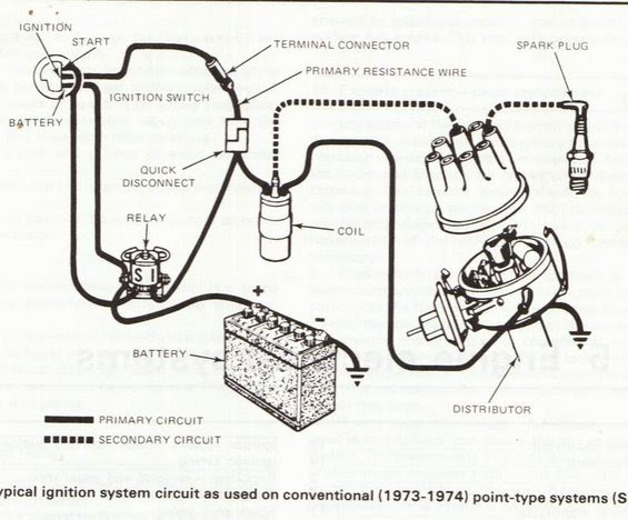
- Solid Lines: Represent wires. The thickness of the line does *not* necessarily indicate wire gauge.
- Dashed Lines: May represent wires or connections that are optional or present only in certain models.
- Battery Symbol: A series of long and short parallel lines. The longer line indicates the positive (+) terminal, and the shorter line indicates the negative (-) terminal.
- Switch Symbol: A break in a line with a movable arm. The position of the arm indicates whether the switch is open (circuit broken) or closed (circuit complete).
- Solenoid Symbol: Usually shown as a coil of wire with terminals. Sometimes also shown as a switch with a coil activating it.
- Ground Symbol: A series of decreasing horizontal lines, indicating a connection to the vehicle's chassis (ground).
- Fuse Symbol: A wavy line or a rectangle with a line through it.
- Connector Symbol: A circle or square where two or more wires connect.
Color Codes: Wiring diagrams use color codes to identify wires. These color codes are usually abbreviated (e.g., "RED" for red, "BLK" for black, "YEL" for yellow). A wire may have a primary color and a stripe of a different color (e.g., "RED/WHT" for a red wire with a white stripe). Always refer to the wiring diagram key for the specific color codes used in your Bronco's model year.
How the Bronco Starter Solenoid Circuit Works
The starting sequence begins when you turn the ignition key to the "start" position. Here's a step-by-step explanation:
- Turning the key to the "start" position sends a low-current signal through a wire (typically a small-gauge wire) from the ignition switch to the starter solenoid.
- This signal energizes the solenoid coil, creating an electromagnetic field.
- The electromagnetic field pulls a plunger inside the solenoid, closing a high-current switch.
- Closing the high-current switch connects the battery directly to the starter motor.
- The starter motor then engages with the engine's flywheel (or flexplate in automatic transmissions), cranking the engine.
- Once the engine starts, releasing the key disengages the starter circuit, stopping the starter motor.
Real-World Use: Troubleshooting Tips
If your Bronco is experiencing starting problems, the wiring diagram can help you pinpoint the source of the issue. Here are some basic troubleshooting steps:
- No Crank, No Click: Check the battery voltage. If the battery is good, check the ignition switch, the wiring between the ignition switch and the solenoid, and the solenoid itself. Use a multimeter to test for voltage at the solenoid when the key is in the "start" position. If there is no voltage, trace the circuit back to the ignition switch.
- No Crank, But You Hear a Click: This usually indicates that the solenoid is engaging but not delivering enough current to the starter motor. Check the battery cable connections at the battery, the solenoid, and the starter motor. Clean and tighten any corroded connections. Also, test the solenoid by bypassing it (carefully jump the two large terminals) to see if the starter motor engages directly. Be very careful when doing this, as it bypasses all safety mechanisms.
- Starter Cranks Slowly: This could be due to a weak battery, corroded connections, or a failing starter motor. Check the battery voltage under load (while cranking the engine). If the voltage drops significantly, the battery is likely weak.
- Starter Stays Engaged After Engine Starts: This is a serious problem that can damage the starter motor. It's usually caused by a faulty solenoid that is not disengaging properly. Replace the solenoid immediately.
Safety Precautions
Working on the electrical system of your Bronco can be dangerous if you're not careful. Here are some important safety precautions:
- Disconnect the Battery: Always disconnect the negative (-) battery cable before working on the electrical system. This will prevent accidental short circuits and electrical shocks.
- Use Proper Tools: Use insulated tools to avoid electrical shocks.
- Be Careful When Testing: When using a multimeter to test for voltage or continuity, be careful not to short-circuit any wires.
- Understand the Wiring Diagram: Make sure you understand the wiring diagram before you start working on the electrical system.
- High Current Components: The battery cables and solenoid connections carry very high current. A short circuit in this area can cause sparks, fires, and burns. Exercise extreme caution when working with these components.
Getting the Diagram
While a general understanding of the system is good, the exact wiring diagram for your specific year and model Ford Bronco is critical. There are several ways to access this information, and we have one ready for you to download and use for your repairs.
The wiring diagram provides a clear and accurate representation of the electrical connections in your Bronco's starting system, making troubleshooting and repairs much easier. With this information, you'll be well-equipped to tackle any starting system issues with confidence. We have the file available for download. You can get it now and use it on your repairs.