Ford Diagram What Wires Go To The Starter Solenoid
Alright, let's talk about Ford starter solenoid wiring. This is a crucial area to understand, especially if you're tackling electrical repairs, upgrading your starting system, or even just trying to diagnose a no-start condition. Whether you're dealing with a classic Mustang, a trusty F-150, or anything in between, the fundamentals remain largely the same. Understanding the Ford starter solenoid wiring diagram empowers you to confidently troubleshoot and repair your vehicle's starting circuit. We've got the diagrams ready for download, but first, let's break down exactly what you're looking at.
Why This Diagram Matters
Let's be honest – automotive wiring can look like a bowl of spaghetti. The diagram is your map. Without it, you're guessing, and guessing when dealing with electricity is a recipe for frustration, damage, or even injury. Specifically, a clear understanding is essential for:
- Troubleshooting No-Start Issues: Is your engine cranking slowly or not at all? The diagram guides you in systematically checking voltage drops, continuity, and component functionality.
- Wiring Upgrades & Modifications: Adding a high-torque starter? Installing an aftermarket alarm system with a starter interrupt? The diagram ensures you're tapping into the correct circuits and not creating shorts or backfeeds.
- Component Replacement: Replacing the solenoid itself, the starter motor, or any related wiring? The diagram provides a visual reference to ensure correct connections.
- Learning Vehicle Electrical Systems: Even if you're not actively wrenching, studying the diagram is a great way to understand the basic principles of automotive electrical circuits.
Key Specs and Main Parts
The Ford starter solenoid system consists of a few key components, each playing a critical role in getting your engine running. Understanding these will make the diagram much easier to interpret:
- Battery: The source of all electrical power. Usually a 12V DC system.
- Ignition Switch: The switch you turn with your key. It signals the solenoid to engage.
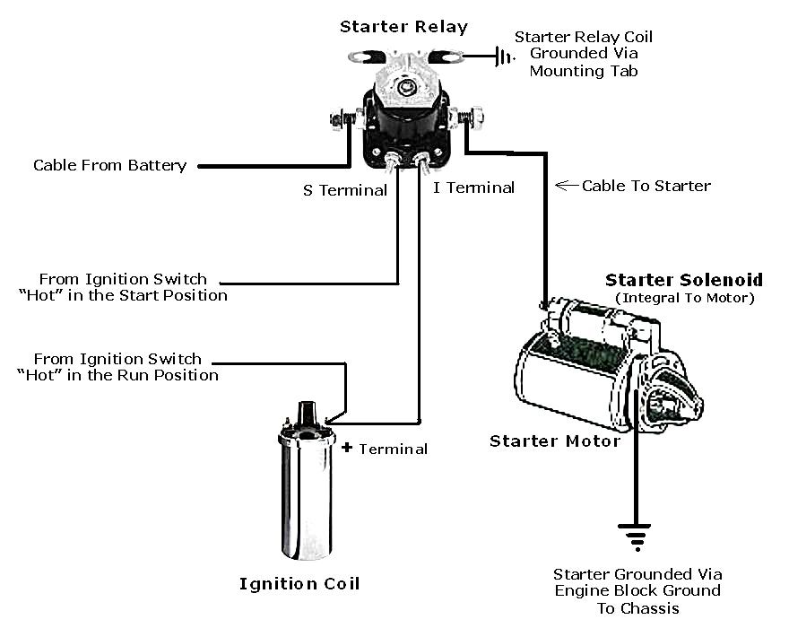
- Starter Solenoid: A heavy-duty relay that closes a high-current circuit to the starter motor. Located on the inner fender (usually) or sometimes mounted directly on the starter itself (later models). It typically has a large post connected directly to the battery and another large post connected to the starter. It also has a small "S" terminal that receives the signal from the ignition switch.
- Starter Motor: The electric motor that spins the engine's crankshaft for starting.
- Grounds: Essential for completing the electrical circuit. Look for connections to the engine block, chassis, and sometimes the body. Bad grounds are a common source of starting problems.
Key Specs to note: Ford starter circuits usually operate at 12 volts DC. Wire gauge is crucial. The heavy-gauge cable (typically 4-gauge or larger) running from the battery to the solenoid and from the solenoid to the starter motor is designed to handle the high amperage draw of the starter. Using too small of a gauge wire can cause overheating and voltage drop.
Decoding the Diagram: Symbols, Lines, and Colors
Let's translate those cryptic lines and symbols:
- Lines:
- Solid Lines: Represent wires. Their thickness often indicates the wire gauge (thicker = larger gauge = more current capacity).
- Dashed Lines: May indicate wires that are part of a harness or are optional for certain models or configurations.
- Symbols:
- Battery: Represented by alternating long and short lines ( _ + _ -). The longer line is the positive (+) terminal, and the shorter line is the negative (-) terminal.
- Switch: A broken line with a pivoting arm. The arm represents the switch position. When the arm connects the line, the switch is closed (circuit completed).
- Solenoid: Usually depicted as a coil of wire with a plunger or armature. Often has a symbol resembling a relay.
- Starter Motor: Represented by a circle with an "M" inside.
- Ground: A series of downward-pointing lines that get progressively shorter. Indicates a connection to the vehicle's chassis (ground).
- Fuse: A squiggly line or a rectangle with a line through it. Indicates a circuit protection device.
- Colors: Wire colors are indicated by abbreviations (e.g., RED, BLK, BLU, YEL). They are critical for identification. Note that wire colors can sometimes fade or change over time, making careful observation essential.
How It Works: The Starting Sequence
Here's the typical sequence of events, as illustrated by the diagram:
- Key Turn: You turn the ignition key to the "start" position. This closes the ignition switch, sending a small electrical signal (usually 12V) to the "S" terminal on the starter solenoid.
- Solenoid Activation: The signal from the ignition switch energizes the solenoid's coil. This creates a magnetic field that pulls a plunger or armature inside the solenoid.
- High-Current Circuit Closure: The plunger closes a set of heavy-duty contacts inside the solenoid, connecting the battery cable directly to the starter motor. This completes the high-current circuit.
- Starter Motor Engagement: The starter motor receives the high current and begins to spin, engaging the starter drive (Bendix) which meshes with the flywheel or flexplate. This spins the engine's crankshaft.
- Engine Start: Once the engine starts, you release the key. The ignition switch opens, de-energizing the solenoid. The solenoid contacts open, disconnecting the starter motor from the battery. The starter motor disengages from the flywheel.
Real-World Use: Basic Troubleshooting Tips
Armed with the diagram, here's how to approach some common starting problems:
- No Crank, No Click:
- Check the battery voltage. Is it at least 12.6 volts?
- Check the ignition switch. Use a multimeter to confirm that 12V is present at the "S" terminal of the solenoid when the key is in the "start" position.
- Check the ground connections. Clean and tighten any corroded ground connections.
- No Crank, Click Sound: This often indicates a problem with the solenoid itself or a very weak battery.
- Test the solenoid. Jump the two large terminals on the solenoid with a heavy-gauge screwdriver (BE CAREFUL! SEE SAFETY SECTION). If the starter cranks, the solenoid is likely faulty.
- Check for voltage drop. Measure the voltage at the starter motor while someone tries to start the car. If the voltage drops significantly (below 10V), there may be excessive resistance in the wiring.
- Slow Crank:
- Check the battery cables and connections for corrosion and looseness.
- Suspect a failing starter motor.
Safety First! Highlighting Risky Components
Working on the starting system involves high current and potentially dangerous components. Observe the following precautions:
- Disconnect the Battery: Always disconnect the negative (-) battery cable before working on any electrical components. This prevents accidental shorts and shocks.
- High Current: The starter circuit carries a significant amount of current. Be extremely careful when testing or jumping terminals. Use insulated tools and avoid touching any exposed metal parts.
- Solenoid Jumping: If you need to jump the solenoid terminals to test the starter, be prepared for sparks! Wear eye protection and gloves. Only do this for a brief test to diagnose the solenoid. Never hold the screwdriver across the terminals for more than a few seconds.
- Fuel Safety: If the engine is cranking but not starting, avoid prolonged cranking. This can flood the engine with fuel and potentially damage the catalytic converter.
By using the diagram and taking necessary safety precautions, you can successfully troubleshoot and repair your Ford's starting system. Remember to take your time, be methodical, and double-check your work. With patience and the right information, you can save yourself a lot of money and gain a valuable understanding of your vehicle's electrical system.
Alright, ready to get your hands on the actual diagrams? We have them available for download right here. They're organized by model year and engine type, so be sure to select the one that matches your specific vehicle. Happy wrenching!
Disclaimer: This information is for educational purposes only and should not be considered a substitute for professional automotive advice. Always consult with a qualified mechanic for any repairs or modifications to your vehicle.