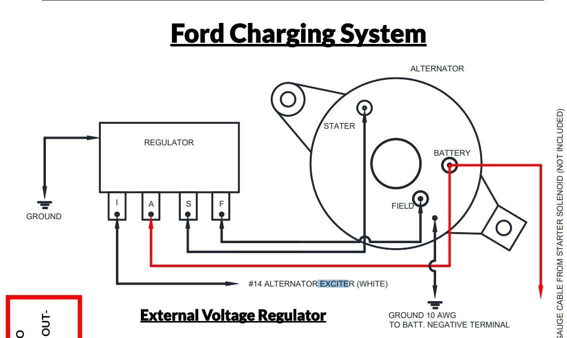
Ford External Voltage Regulator Wiring Diagram
The external voltage regulator, a now somewhat archaic but still relevant component in many classic Ford vehicles (and some more recent industrial applications), plays a critical role in maintaining a stable voltage output from the alternator to the vehicle's electrical system. Understanding the wiring diagram for this regulator is essential for proper diagnosis, repair, and even modification of these systems. This article delves into the specifics of Ford's external voltage regulator wiring, providing you, the experienced DIYer, with the knowledge needed to confidently tackle related electrical tasks.
Purpose and Importance of the Wiring Diagram
Why bother learning about this seemingly outdated technology? Several reasons make understanding the Ford external voltage regulator wiring diagram valuable:
- Diagnosis and Repair: If your classic Ford is experiencing charging issues (e.g., dim headlights, a failing battery), the voltage regulator is a prime suspect. A wiring diagram lets you systematically trace circuits, test connections, and pinpoint the faulty component.
- Restoration and Modification: Restoring a vintage Ford often involves dealing with deteriorated wiring. A wiring diagram is crucial for accurately replacing harnesses and ensuring proper connections. Similarly, if you're swapping in a different alternator or modifying the charging system, understanding the existing wiring is paramount.
- Learning and Understanding: Even if you don't own a classic Ford, studying the external voltage regulator system provides valuable insight into how charging systems work in general. You’ll better grasp the concepts of voltage regulation, field current control, and feedback loops, benefiting your understanding of modern systems too.
Key Specs and Main Parts
Before diving into the diagram, let's define the key components involved. A Ford external voltage regulator system typically consists of the following parts:
- Alternator: The source of electrical power for the vehicle. It converts mechanical energy from the engine into AC electricity, which is then rectified to DC. The alternator's output voltage varies depending on engine speed and load.
- Voltage Regulator: The brain of the system. It monitors the alternator's output voltage and adjusts the field current to maintain a stable voltage (typically around 13.8-14.5 volts) regardless of engine speed or electrical load.
- Battery: Provides initial power for starting and acts as a buffer for the electrical system, absorbing voltage fluctuations.
- Ammeter/Voltmeter: Indicates the charging or discharging current/voltage of the system.
- Wiring Harness: Connects all components, providing the electrical pathways for power and control signals.
The specs of the voltage regulator (and alternator) are crucial. Make sure the replacement regulator is designed for your specific alternator type and voltage requirements. Using the wrong regulator can damage the alternator or lead to over/undercharging of the battery.
Symbols and Legend: Decoding the Diagram
Wiring diagrams use standardized symbols to represent electrical components and connections. Understanding these symbols is essential for interpreting the diagram correctly. Here's a breakdown of common symbols you'll encounter:
- Lines: Represent wires or conductors. Solid lines typically indicate a positive wire, while dashed lines may indicate a ground wire or a wire carrying a control signal. The thickness of the line often indicates the wire gauge (size).
- Colors: Each wire is assigned a specific color. Ford used standardized color codes, but these can fade or change over time. The diagram will usually include a color code legend, such as "Red = Battery Positive," "Black = Ground," "Green = Field," etc.
- Circles: Often represent components, such as resistors, capacitors, or diodes. The specific symbol inside the circle denotes the type of component.
- Rectangles: Can represent relays, switches, or even the voltage regulator itself. Internal components within the rectangle may be shown schematically.
- Ground Symbol: A downward-pointing triangle or a series of horizontal lines indicates a connection to the vehicle's chassis ground.
- Connectors: Represented by various shapes, often a square with an arrow pointing to the wire entering. These show where wires are joined using a physical connector.
Understanding the color coding is incredibly important. For example, a wire marked “#14 Blue/Red Stripe” would indicate a 14-gauge wire that is primarily blue with a red stripe running along its length. These colors are not arbitrary; they were used to differentiate circuits within the car.
How It Works: Understanding the Charging System
The external voltage regulator works by controlling the amount of current flowing through the field winding of the alternator. The field winding is an electromagnet that, when energized, creates a magnetic field that interacts with the rotating parts of the alternator to generate electricity.
- Voltage Sensing: The regulator constantly monitors the voltage at the battery (or a designated sensing point).
- Comparison: The regulator compares the sensed voltage to a pre-set reference voltage (typically around 14 volts).
- Field Current Adjustment: If the sensed voltage is too low, the regulator increases the current flowing through the field winding, strengthening the magnetic field and causing the alternator to produce more electricity. Conversely, if the sensed voltage is too high, the regulator reduces the field current, weakening the magnetic field and reducing the alternator's output.
- Feedback Loop: This process creates a feedback loop, continuously adjusting the field current to maintain a stable output voltage.
The older mechanical regulators used points (like ignition points) to rapidly switch the field current on and off, creating an average current that controlled the alternator's output. Later electronic regulators use transistors to achieve the same effect more efficiently and reliably.
Real-World Use: Troubleshooting Tips
Here are some basic troubleshooting tips using the wiring diagram:
- No Charging: Check the voltage at the battery with the engine running. If it's significantly below 13.8 volts, start by verifying the alternator's output (B+ terminal). Then, trace the wiring from the alternator to the voltage regulator and battery, looking for breaks, corrosion, or loose connections. Use a multimeter to check for voltage drops across connections.
- Overcharging: If the voltage is consistently above 14.5 volts, the voltage regulator is likely faulty and needs to be replaced. Before replacing it, check the ground connections to the regulator and alternator. A bad ground can cause erratic voltage readings.
- Erratic Charging: Intermittent charging problems can be caused by loose connections, corroded terminals, or a failing voltage regulator. Carefully inspect all wiring and connections. Use a contact cleaner to remove corrosion.
- Wiring Diagram Verification: Always compare the wiring in your vehicle to the diagram. Previous owners may have made modifications or repairs, leading to incorrect wiring.
A simple test is to bypass the regulator (temporarily and with extreme caution!) by directly connecting the field terminal to the battery (through a fuse!). If the alternator now charges strongly, the regulator is likely bad. DO NOT run the vehicle like this for more than a very brief test, as it will overcharge the battery.
Safety First: Handling Electrical Components
Working with electrical systems can be dangerous. Observe the following safety precautions:
- Disconnect the Battery: Always disconnect the negative battery cable before working on the electrical system to prevent short circuits and potential damage.
- Use Proper Tools: Use insulated tools to avoid accidental shorts.
- Work in a Well-Ventilated Area: Some electrical components can produce fumes when overheated.
- Be Aware of Capacitors: Capacitors can store a charge even after the battery is disconnected. Discharge them carefully before handling.
- Never Work Alone: Have someone nearby in case of an emergency.
The alternator and regulator are relatively low-voltage DC devices, but shorts can still cause significant heat and potential fires. Always be mindful of where you're placing tools and wires.
Understanding the Ford external voltage regulator wiring diagram empowers you to diagnose and repair charging system issues on your classic Ford. By familiarizing yourself with the components, symbols, and troubleshooting techniques outlined in this article, you can confidently tackle these tasks and keep your vintage vehicle running smoothly.
We have a high-resolution PDF file of a typical Ford external voltage regulator wiring diagram available for download. Feel free to reach out to us, and we'll provide you with the link.