
Ford F150 Catalytic Converter Diagram
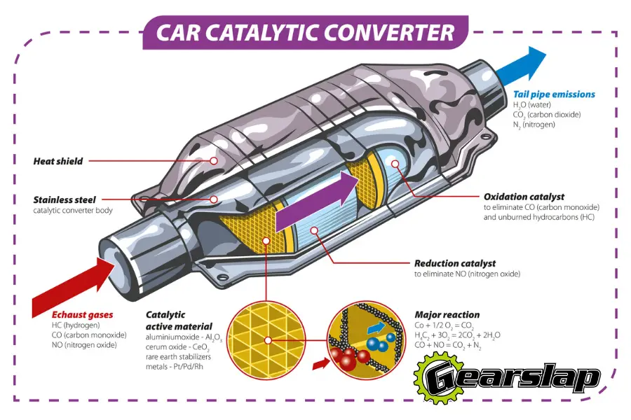
Let's dive into the catalytic converter system of your Ford F-150. This guide, focused on understanding a typical catalytic converter diagram, is geared towards experienced DIYers and car enthusiasts who want to understand how their vehicle's emission control system works. We'll break down the components, how they interact, and how to troubleshoot common issues. A solid understanding of your F-150's catalytic converter system empowers you to make informed decisions about repairs, upgrades, and maintenance.
Purpose of Understanding the Catalytic Converter Diagram
Why bother understanding a catalytic converter diagram? There are several compelling reasons:
- Diagnostics and Repair: The diagram provides a visual roadmap for tracing components and connections. This is invaluable when diagnosing issues like P0420 (Catalyst System Efficiency Below Threshold) or other related diagnostic trouble codes (DTCs).
- Component Identification: Accurately identifying each component – from the oxygen sensors (O2 sensors) to the converter itself – ensures you're ordering the correct parts when making repairs.
- System Understanding: Gaining a deeper understanding of the entire exhaust and emissions control system. How the sensors influence the engine control unit (ECU), and how the converter plays its part.
- Modification and Upgrades: If you're considering modifications like aftermarket exhaust systems, understanding the catalytic converter layout is crucial for compatibility and legality (especially regarding emissions standards).
- DIY Confidence: A well-understood diagram boosts your confidence to tackle DIY repairs, saving you money on labor costs.
Key Specs and Main Parts
The catalytic converter system in an F-150 is relatively straightforward, but understanding the key components is essential.
Main Components:
- Exhaust Manifold: This collects exhaust gases directly from the engine's cylinders and funnels them into the exhaust system.
- Oxygen Sensors (O2 Sensors): These sensors measure the oxygen content in the exhaust gas. There are typically two types:
- Upstream (Pre-Converter) O2 Sensor: Located before the catalytic converter, this sensor measures the oxygen content before the exhaust gases enter the converter. This information is crucial for the ECU to adjust the air-fuel ratio.
- Downstream (Post-Converter) O2 Sensor: Located after the catalytic converter, this sensor measures the oxygen content after the gases have passed through the converter. This reading is used to monitor the converter's efficiency.
- Catalytic Converter: This is the heart of the system. It contains a catalyst (usually platinum, palladium, and rhodium) that facilitates chemical reactions to convert harmful pollutants into less harmful substances.
- Exhaust Pipes: These pipes connect the various components of the exhaust system.
- Muffler: Reduces exhaust noise.
- Tailpipe: The final outlet for exhaust gases.
Key Specifications:
It is important to consult the service manual specific to your F-150's year and engine configuration for precise specifications.
- Catalytic Converter Type: Most F-150s use a three-way catalytic converter, which reduces hydrocarbons (HC), carbon monoxide (CO), and nitrogen oxides (NOx).
- O2 Sensor Types: Typically, zirconia or titania sensors are used.
- Operating Temperature: Catalytic converters require high operating temperatures (around 400-800°C) to function effectively.
- Material: Exhaust components are usually made of stainless steel or aluminized steel to resist corrosion.
Symbols and Conventions in the Diagram
Understanding the symbols used in the catalytic converter diagram is crucial for interpreting it correctly. Common symbols include:
- Solid Lines: Represent exhaust pipes or tubing. The thickness of the line might indicate the diameter of the pipe.
- Dashed Lines: Often indicate electrical wiring or vacuum lines related to the O2 sensors or other sensors that might influence the engine's fueling and timing.
- Rectangles: Typically represent components like the catalytic converter, muffler, or resonators.
- Circles or Ovals: Can represent sensors, such as O2 sensors. Look for labels indicating "O2S11" (Oxygen Sensor, Bank 1, Sensor 1 - upstream) or "O2S12" (Oxygen Sensor, Bank 1, Sensor 2 - downstream).
- Arrows: Indicate the direction of exhaust gas flow.
- Color Coding: Some diagrams use color coding to differentiate between different types of lines (e.g., red for hot exhaust, blue for vacuum lines, green for electrical grounds).
How It Works
The catalytic converter system is an integral part of the F-150's emissions control system. Here's a breakdown of how it works:
- Exhaust Gas Production: Combustion in the engine produces harmful gases, including hydrocarbons (HC), carbon monoxide (CO), and nitrogen oxides (NOx).
- O2 Sensor Feedback: The upstream O2 sensor monitors the oxygen content in the exhaust gas before it enters the catalytic converter. This data is sent to the ECU.
- ECU Adjustments: Based on the upstream O2 sensor readings, the ECU adjusts the air-fuel mixture entering the engine to maintain an optimal stoichiometric ratio (around 14.7:1). This ensures efficient combustion and minimizes pollutant formation.
- Catalytic Conversion: The exhaust gases enter the catalytic converter. The catalyst inside facilitates chemical reactions that convert harmful pollutants into less harmful substances:
- Hydrocarbons (HC) are oxidized into water (H2O) and carbon dioxide (CO2).
- Carbon monoxide (CO) is oxidized into carbon dioxide (CO2).
- Nitrogen oxides (NOx) are reduced into nitrogen (N2) and oxygen (O2).
- Downstream O2 Sensor Monitoring: The downstream O2 sensor monitors the oxygen content after the gases have passed through the catalytic converter. This reading is compared to the upstream O2 sensor reading. A properly functioning catalytic converter will significantly reduce the oxygen content.
- Efficiency Monitoring: If the downstream O2 sensor reading is too similar to the upstream reading, it indicates that the catalytic converter is not functioning efficiently, potentially triggering a P0420 code or similar DTC.
Real-World Use: Basic Troubleshooting Tips
Here are some basic troubleshooting tips using the catalytic converter diagram:
- P0420 Code (Catalyst System Efficiency Below Threshold):
- Check for exhaust leaks before the catalytic converter. Leaks can introduce excess air, affecting the O2 sensor readings.
- Inspect the O2 sensors. Use a multimeter to check their resistance and voltage output. A faulty O2 sensor can send incorrect data to the ECU.
- Visually inspect the catalytic converter for physical damage.
- If the O2 sensors are functioning correctly and there are no exhaust leaks, the catalytic converter itself might be failing.
- Rough Running Engine: A clogged catalytic converter can restrict exhaust flow, leading to a rough running engine. Check for excessive backpressure.
- O2 Sensor Codes: Use the diagram to locate and identify the specific O2 sensor indicated by the DTC. Check the wiring and connectors for damage. Test the sensor's functionality.
- Exhaust Leaks: Visually inspect the exhaust pipes and connections for signs of leaks (e.g., rust, soot). Listen for hissing or roaring sounds coming from the exhaust system.
Safety Considerations
Working on the exhaust system involves several safety risks:
- Hot Exhaust Components: Exhaust components can be extremely hot, even long after the engine has been turned off. Allow the system to cool completely before working on it. Use heat-resistant gloves.
- Exhaust Fumes: Exhaust fumes contain harmful gases. Work in a well-ventilated area or use a respirator.
- Lifting the Vehicle: Always use jack stands to support the vehicle when working underneath it. Never rely solely on a jack.
- Electrical Components: When working on O2 sensors, disconnect the negative battery terminal to prevent electrical shocks or damage to the ECU.
- Catalytic Converter Core: The internal structure of the catalytic converter contains potentially hazardous materials. Avoid inhaling dust or debris if the converter is damaged.
With careful observation, and the right tools, understanding the Ford F-150 catalytic converter diagram gives you a solid foundation for diagnosis, repair, and modification.
We have a high-resolution version of a typical Ford F-150 catalytic converter diagram available for download. Contact us and we will provide you with access to the file.