
Ford F150 Stereo Wiring Harness Adapter
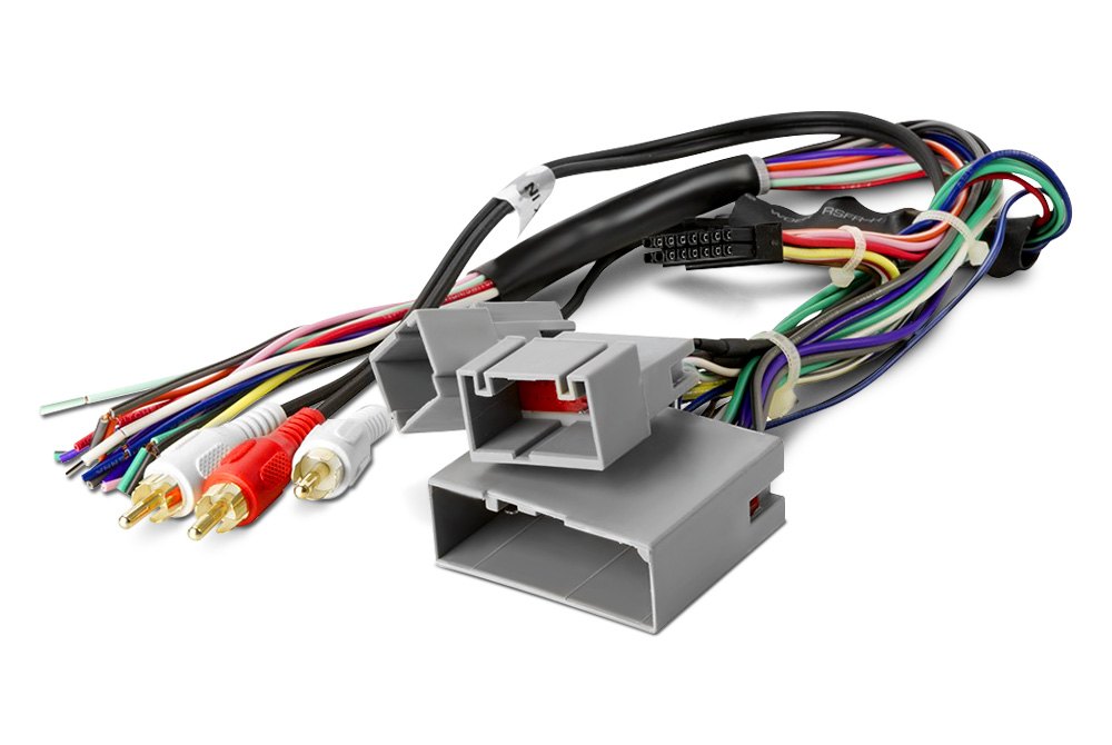
Alright, let's talk about something that's crucial if you're planning on upgrading the stereo in your Ford F-150: the stereo wiring harness adapter. Whether you're replacing a blown speaker, adding a subwoofer, or completely overhauling your audio system, understanding this adapter is key to a clean, professional, and, most importantly, functional installation. This article will break down the technical aspects of the F-150 stereo wiring harness adapter, empowering you to tackle your audio projects with confidence.
Purpose of the F-150 Stereo Wiring Harness Adapter
The main reason we need a stereo wiring harness adapter is to avoid cutting or splicing into the factory wiring of your F-150. Think of it as a translator between the new aftermarket stereo and the existing electrical system in your truck. Without it, you'd be faced with a tangled mess of wires, potentially damaging your truck's electrical system and making it difficult to revert back to the original factory stereo. Using the adapter ensures a reversible and non-destructive installation.
Specifically, the adapter serves several critical functions:
- Provides Power: It taps into the existing power wires to supply the aftermarket stereo with the necessary voltage (usually 12V DC).
- Delivers Ground: It connects the stereo's ground wire to the vehicle's chassis, ensuring proper electrical grounding.
- Connects Speakers: It links the stereo's speaker outputs to the vehicle's speaker wires, delivering audio to each speaker location.
- Provides Accessory Power: This is usually a switched 12V source that powers on the stereo only when the ignition is turned on. This prevents battery drain.
- Retains Steering Wheel Controls (in some cases): More advanced adapters can maintain the functionality of your steering wheel audio controls, allowing you to adjust volume, change tracks, and answer calls without taking your hands off the wheel. This often requires a separate module.
Key Specs and Main Parts
Before diving into the wiring diagram, let's familiarize ourselves with the key components:
- The Vehicle-Specific Connector: This end plugs directly into the factory stereo wiring harness in your F-150. It's designed to fit perfectly and securely, preventing any loose connections.
- The Aftermarket Stereo Connector: This end typically uses a standard ISO connector, which is compatible with most aftermarket stereos.
- Color-Coded Wires: Each wire is color-coded according to industry standards (usually the Electronic Industries Association, or EIA) to indicate its function (e.g., power, ground, speaker).
- Wire Gauge: The thickness of the wire, measured in AWG (American Wire Gauge). A lower AWG number indicates a thicker wire, capable of carrying more current. Generally, 16-18 AWG is sufficient for most stereo applications.
- Fuse Tap (Optional): Some adapters include a fuse tap, allowing you to safely tap into an existing fuse circuit for accessory power.
Understanding the Wiring Diagram: Symbols, Lines, and Colors
The wiring diagram is your roadmap for connecting the adapter to your F-150 and the new stereo. Here's how to decipher it:
Symbols
- Solid Lines: Represent wires.
- Dashed Lines: May indicate a shielded wire or a connection that's not always present (depending on the F-150 trim level).
- Circles: Represent connectors or terminal points.
- Resistors: (Zig-zag line) Indicates a resistor in the circuit, potentially for signal conditioning or voltage dropping.
- Capacitors: (Two parallel lines) Indicates a capacitor, potentially used for filtering noise from the power supply.
- Ground Symbol: (Usually three horizontal lines tapering downwards) Indicates a connection to the vehicle's chassis ground.
Colors
Color codes are crucial for identifying wire functions. While there can be slight variations depending on the F-150 model year and trim level, some common color codes include:
- Red: 12V Constant Power (always on, even when the ignition is off)
- Yellow: 12V Switched Power (only on when the ignition is on)
- Black: Ground
- White: Left Front Speaker (+)
- White with Black Stripe: Left Front Speaker (-)
- Gray: Right Front Speaker (+)
- Gray with Black Stripe: Right Front Speaker (-)
- Green: Left Rear Speaker (+)
- Green with Black Stripe: Left Rear Speaker (-)
- Purple: Right Rear Speaker (+)
- Purple with Black Stripe: Right Rear Speaker (-)
- Blue: Remote Turn-On (for amplifiers)
- Orange: Illumination (dims the stereo display when headlights are on)
Important: Always double-check the color codes against the wiring diagram specific to your F-150 model year and trim level. Do not rely solely on memory.
How It Works
The adapter essentially maps the wires from your F-150's factory harness to the corresponding connections on your aftermarket stereo. The wiring diagram shows you exactly which wire from the vehicle connector needs to be connected to which wire on the aftermarket stereo connector. This ensures that the stereo receives the correct power, ground, and speaker signals. For instance, the diagram will show you that the red wire from the vehicle connector (12V Constant) needs to be connected to the red wire on the stereo connector. Similarly, the white wire from the vehicle connector (Left Front Speaker +) needs to be connected to the white wire on the stereo connector.
Real-World Use: Basic Troubleshooting Tips
Even with a wiring diagram, things can sometimes go wrong. Here are a few common troubleshooting tips:
- No Power: Check the fuse for the stereo circuit in your F-150's fuse box. Use a multimeter to verify that you're getting 12V on the red and yellow wires from the adapter. Also, ensure the black wire is properly grounded.
- No Sound: Double-check all speaker wire connections. Ensure that the positive (+) and negative (-) wires are correctly connected for each speaker. A swapped polarity can cause phase cancellation, resulting in weak or distorted sound.
- Stereo Turns Off Randomly: This could be due to a loose connection or a faulty ground. Inspect all connections carefully and ensure they are secure.
- Steering Wheel Controls Not Working: If you're using an adapter to retain steering wheel controls, make sure it's properly programmed for your F-150 model and aftermarket stereo. Refer to the adapter's instructions for programming details.
Safety Considerations
Working with automotive electrical systems can be dangerous. Here are some crucial safety precautions:
- Disconnect the Battery: Before starting any wiring work, disconnect the negative (-) terminal of your F-150's battery. This will prevent accidental short circuits and potential electrical shocks.
- Use Proper Tools: Use insulated crimping tools, wire strippers, and a multimeter. Avoid using household tools, as they may not be suitable for automotive wiring.
- Inspect Wires: Before connecting any wires, carefully inspect them for any damage or exposed conductors. Replace any damaged wires immediately.
- Avoid Overloading Circuits: Do not tap into existing circuits that are already heavily loaded. This can cause the fuse to blow or even damage the wiring.
- Airbags: Be especially careful around airbags. Incorrect wiring can cause them to deploy unexpectedly. If you're unsure about working near airbags, consult a professional.
Important Note: The most dangerous component is your F-150's battery. Even a small mistake can lead to a short circuit and potential fire. Exercise extreme caution.
By carefully following the wiring diagram, using the correct tools, and adhering to safety precautions, you can successfully install or repair your F-150's stereo system. Remember, patience and attention to detail are key to a successful outcome.
We have a detailed wiring diagram file specifically for Ford F-150 models that can help you further. You can download the file here.