
Ford F250 Radio Wiring Harness Diagram
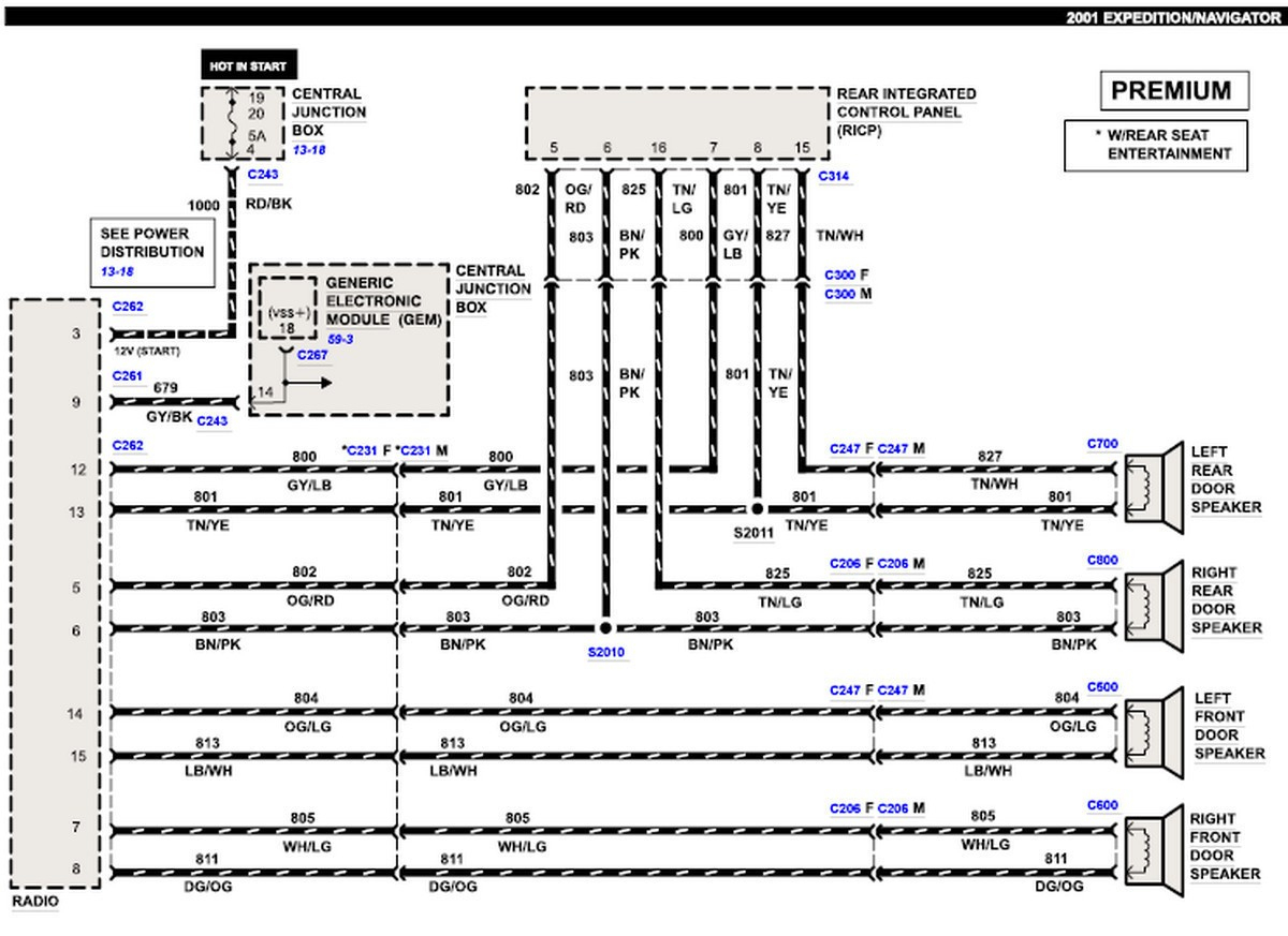
The Ford F-250, a workhorse of a truck, often sees modifications and upgrades to its audio system. Understanding the radio wiring harness diagram is crucial for everything from replacing a blown fuse to installing a new head unit, amplifier, or speaker system. Without it, you're essentially navigating a maze blindfolded, risking damage to your vehicle's electronics or even personal injury.
Purpose of the Radio Wiring Harness Diagram
This diagram acts as a roadmap for your F-250's audio system wiring. Its purpose extends beyond simple radio replacement. You might need it for:
- Troubleshooting Audio Problems: Identify shorts, open circuits, or miswired connections that cause speakers to cut out, the radio to not power on, or other audio malfunctions.
- Installing Aftermarket Equipment: Connecting a new head unit, amplifier, subwoofer, or speakers requires tapping into the factory wiring harness. The diagram shows you where each wire goes.
- Repairing Damaged Wiring: Rodents, wear and tear, or accidents can damage wiring. The diagram helps you locate the damaged sections and splice in new wires correctly.
- Understanding the System: Even if you're not actively working on the system, the diagram offers valuable insight into how the radio and related components are wired and interconnected.
Key Specs and Main Parts of the F-250 Radio Wiring Harness
The specifics of the radio wiring harness vary slightly depending on the F-250's year, trim level, and options package (e.g., with or without factory amplifier, navigation system, or satellite radio). However, some key components and connections are almost always present. Here's a general overview:
- Power Wires:
- 12V Constant (Battery): Provides continuous power to the radio, allowing it to retain memory and settings. This wire is typically a thicker gauge and often colored yellow.
- 12V Switched (Ignition): Powers on the radio when the ignition is turned on. This wire is typically red.
- Ground: Completes the electrical circuit, providing a return path for the current. Usually black or brown.
- Speaker Wires:
- Each speaker (front left, front right, rear left, rear right) has two wires: a positive (+) and a negative (-) connection. These wires are usually paired and color-coded (e.g., white/black for left front + and white for left front -). Proper polarity is crucial for sound quality.
- Antenna Wire: A coaxial cable that connects the radio to the antenna, allowing it to receive radio signals.
- Illumination Wire: Dims the radio display when the headlights are turned on. Often orange or white/blue.
- Remote Turn-On (Amplifier): A 12V signal that turns on an aftermarket amplifier when the radio is powered on. Usually blue.
- Steering Wheel Control Wires: Allow the steering wheel buttons to control the radio functions. These typically require an adapter for aftermarket radios.
- Data Bus Wires (CAN Bus): In newer F-250s, the radio communicates with other vehicle systems via a CAN (Controller Area Network) bus. These wires carry digital information and require specialized adapters for aftermarket integration.
Decoding the Wiring Harness Diagram: Symbols, Lines, and Colors
The wiring diagram uses a standardized set of symbols, lines, and colors to represent electrical components and connections. Understanding these conventions is key to interpreting the diagram correctly.
- Lines: Solid lines represent wires. Thicker lines usually indicate wires that carry more current (e.g., power wires). Dotted lines may indicate shielded wires or less critical connections.
- Colors: Each wire is assigned a specific color code (e.g., red, black, yellow, blue, green, white). These color codes are crucial for identifying the correct wires in the harness.
- Symbols:
- Resistor: A zigzag line.
- Capacitor: Two parallel lines.
- Diode: A triangle pointing to a line.
- Ground: A series of downward-pointing lines or a symbol resembling an upside-down Christmas tree.
- Fuse: A squiggly line inside a rectangle.
- Connector: Represented by various shapes indicating how wires are joined together. Often depicted as a male and female fitting.
- Wire Gauge: The diagram may indicate the wire gauge (e.g., 16 AWG, 18 AWG), which specifies the wire's thickness and current-carrying capacity. Using the correct gauge is important for safety and performance.
How It Works: Tracing the Signal Path
The radio wiring harness is the central hub for the audio system. Power enters the radio through the 12V constant and 12V switched wires. When the ignition is turned on, the radio powers up and processes audio signals from various sources (antenna, CD player, USB input, etc.). These signals are then amplified internally or externally and sent to the speakers through the speaker wires. The ground wire provides a return path for the current, completing the circuit.
In systems with factory amplifiers, the radio sends a low-level audio signal to the amplifier through RCA cables or dedicated wiring. The amplifier then boosts the signal and sends it to the speakers. The remote turn-on wire ensures that the amplifier powers on only when the radio is active.
Real-World Use: Basic Troubleshooting Tips
Here are a few basic troubleshooting scenarios where the radio wiring diagram can be invaluable:
- Radio Won't Turn On: Check the 12V constant and 12V switched wires for power using a multimeter. Verify that the ground wire is properly connected. Also, check the radio fuse in the fuse box. Always disconnect the negative battery terminal before working on electrical components.
- Speakers Not Working: Check the speaker wires for continuity using a multimeter. Ensure that the speakers are properly connected and not blown. If you have an amplifier, verify that it's powered on and receiving a signal from the radio.
- Static or Distortion: Check the antenna connection for corrosion or damage. Ensure that the speaker wires are not shorted to ground.
- Incorrect Wiring: Double-check the wiring diagram to confirm that all wires are connected to the correct terminals. Incorrect wiring can damage the radio, speakers, or other components.
Safety: Working with Risky Components
Working with automotive electrical systems can be dangerous. Always follow these safety precautions:
- Disconnect the Negative Battery Terminal: This is the most important safety precaution. Disconnecting the battery prevents accidental shorts and electrical shocks.
- Use Proper Tools: Use insulated tools designed for automotive electrical work.
- Avoid Working in Wet Conditions: Water conducts electricity and can increase the risk of electric shock.
- Identify High-Current Circuits: The 12V constant wire carries a significant amount of current. Avoid shorting this wire to ground.
- Work in a Well-Ventilated Area: Some electrical components can release harmful fumes when overheated.
Understanding your Ford F-250's radio wiring harness diagram empowers you to diagnose problems, perform upgrades, and maintain your audio system with confidence. By carefully studying the diagram and following safe practices, you can achieve professional-quality results.
We have a comprehensive wiring diagram available for download. It's a valuable resource for any F-250 owner looking to work on their audio system. The download includes detailed color coding and component locations.