Ford F350 Wiring Diagram Tail Lights
Alright, let's dive into the wiring diagram for the tail lights on your Ford F-350. This isn't just some abstract schematic; it's the roadmap to understanding, troubleshooting, and even modifying the electrical system responsible for your truck's rear illumination. Whether you're chasing down a pesky flickering brake light, planning to install a custom light bar, or simply want to understand how your truck is wired, this diagram is your key.
Why You Need This Diagram
The Ford F-350 tail light wiring diagram is an invaluable tool for several reasons:
- Troubleshooting Electrical Issues: Diagnosing lighting problems can be frustrating without a clear understanding of the circuit. The diagram shows you the path of electricity, allowing you to pinpoint breaks, shorts, or faulty components.
- Performing Repairs: Need to replace a damaged connector or splice a wire? The diagram guides you to the correct wires and their functions.
- Adding Accessories: Integrating new tail lights, backup cameras, or trailer wiring requires knowing which wires to tap into and what their functions are.
- Understanding Your Vehicle: Even if you're not currently facing a problem, studying the diagram can deepen your understanding of your truck's electrical system and make you a more informed owner.
Key Specs and Main Parts of the Tail Light Circuit
Before we get into the diagram itself, let's cover the key components involved in the F-350's tail light circuit. These are the players in our electrical drama:
- Battery: The source of electrical power for the entire system. Typically a 12V lead-acid battery.
- Fuse(s): These are critical safety devices that protect the circuit from overloads. If too much current flows through the circuit (due to a short, for example), the fuse will blow, interrupting the flow and preventing damage. The F-350 typically has fuses dedicated to the tail lights, brake lights, and turn signals. Check your owner's manual for specific fuse locations and amperage ratings.
- Light Switch/Headlight Switch: This is the primary control point for activating the tail lights.
- Turn Signal Switch: Located in the steering column, this switch controls the left and right turn signals.
- Brake Light Switch: Situated near the brake pedal, this switch activates the brake lights when the pedal is pressed.
- Wiring Harness: The network of wires that connects all the components. These are bundled together and often protected by a plastic sheathing.
- Connectors: These are used to connect different sections of the wiring harness and to connect wires to the tail light assemblies themselves.
- Tail Light Assembly: This includes the brake light, turn signal, running light, and sometimes a backup light. The assembly contains the bulbs (or LEDs) and reflectors.
- Bulbs/LEDs: The light-emitting elements. Older F-350s use incandescent bulbs, while newer models often use LEDs.
- Grounds: Crucially important for completing the circuit. The tail light assemblies are grounded to the truck's frame. A poor ground is a common cause of tail light problems.
- Trailer Wiring (if equipped): If your F-350 has a trailer hitch, it will also have a trailer wiring connector that provides signals for the trailer's tail lights, brake lights, and turn signals.
Understanding the Wiring Diagram Symbols
A wiring diagram is a symbolic representation of the electrical circuit. Understanding the symbols is crucial for interpreting the diagram.
- Lines: Represent wires. A solid line typically indicates a single wire. Dashed lines may represent shielded wires or connections to other circuits.
- Colors: Wires are typically color-coded to help identify their function. Ford uses a standardized color-coding system. For example, a brown wire might be for the tail lights, while a green wire might be for the right turn signal. The diagram will have a legend indicating what each color represents.
- Circles with Numbers: Usually indicate connectors. The number inside the circle is often a pin number on the connector.
- Rectangles: Represent components such as switches, relays, or modules.
- Zigzag Line: Represents a resistor.
- Ground Symbol: Looks like an upside-down tree. Indicates a connection to the vehicle's chassis (ground).
- Fuse Symbol: Looks like a squiggly line inside a rectangle. Indicates a fuse.
- Light Bulb Symbol: Represents a light bulb.
- Arrows: Indicate the direction of current flow (though this is less common in simpler diagrams).
The wiring diagram will also use abbreviations. Common abbreviations include: GND (Ground), B+ (Battery Positive), SIG (Signal), LT (Left), RT (Right), BK (Black), WH (White), RD (Red), GR (Green), YL (Yellow), BL (Blue), BN (Brown), OR (Orange), PK (Pink), VT (Violet), GY (Gray). These abbreviations will be defined in the diagram's legend.
How It Works: The Tail Light Circuit in Action
Let's trace the path of electricity to illuminate your tail lights:
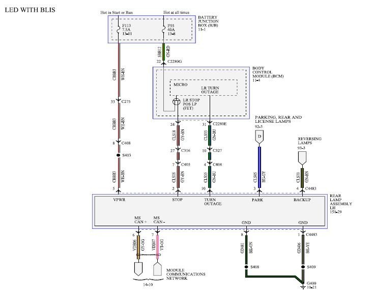
- Running Lights: When you turn on the headlight switch, power flows from the battery, through a fuse, to the headlight switch. The headlight switch then sends power to the tail light circuit. This power flows through the wiring harness to the tail light assemblies, illuminating the running lights (also called parking lights).
- Brake Lights: When you press the brake pedal, the brake light switch closes, completing a circuit that sends power from the battery (again, through a fuse) directly to the brake light filaments in the tail light assemblies.
- Turn Signals: When you activate the turn signal switch, it sends a pulsing signal to the appropriate tail light assembly (left or right). This causes the turn signal bulb to flash on and off. The flasher unit controls the timing of the pulses.
- Ground: Crucially, all circuits must have a complete path for electricity to flow. After passing through the bulb or LED, the electricity returns to the battery through the vehicle's chassis (ground).
Real-World Use: Basic Troubleshooting Tips
Here are some common tail light problems and how the wiring diagram can help you diagnose them:
- No Tail Lights: Check the fuses first. If the fuses are good, use a multimeter to check for voltage at the tail light sockets. If there's no voltage, trace the wiring back to the headlight switch, checking for breaks or loose connections along the way. The diagram will show you the wire colors and connector locations.
- One Tail Light Not Working: Start by checking the bulb. If the bulb is good, check for voltage at the socket. If there's no voltage, check the wiring harness for breaks or loose connections. Pay close attention to the ground connection. A corroded ground can cause a single light to fail.
- Brake Lights Not Working: Check the brake light switch. You can use a multimeter to test the switch for continuity. If the switch is good, check the wiring from the switch to the tail light assemblies.
- Turn Signals Not Working: If both turn signals are not working, check the flasher unit. If only one turn signal is not working, check the bulb, the wiring harness, and the turn signal switch.
- All the lights are dim/flickering: This is almost always a ground issue. Clean and tighten all ground connections in the tail light circuit.
Important Tools: A multimeter, a test light, wire strippers, crimpers, and a good set of automotive tools are essential for troubleshooting electrical problems. Also, dielectric grease is your friend! Apply it to connectors to prevent corrosion.
Safety First!
Working with automotive electrical systems can be dangerous. Always disconnect the negative terminal of the battery before working on any electrical components. Never work on electrical systems while the engine is running. Be especially careful when working around the airbag system, as improper handling can cause it to deploy. If you are not comfortable working with electrical systems, it's best to consult a qualified mechanic.
High-Risk Components: The airbag system and the ABS (Anti-lock Braking System) are sensitive and potentially dangerous. Avoid probing wires or connectors related to these systems unless you are specifically trained to do so.
Get Your Diagram
Here is the link to download the Ford F350 Tail Light Wiring Diagram. Download Here
Having the correct wiring diagram for your specific year and model F-350 is essential. Variations exist between model years and trim levels, so ensure the diagram matches your truck's configuration. With the right diagram and a methodical approach, you can confidently diagnose and repair your F-350's tail light issues.