Ford Internal Regulator 3 Wire Alternator Wiring Diagram
Understanding the Ford internal regulator 3-wire alternator wiring diagram is crucial for anyone tackling electrical repairs, upgrades, or even diagnosing simple charging problems on classic Ford vehicles. Many older Ford cars and trucks utilized this relatively simple but effective charging system. Being able to interpret the diagram allows you to confidently troubleshoot issues, modify your electrical system, or replace components without fear of damaging your vehicle or yourself. This article serves as a comprehensive guide, explaining the diagram's purpose, key components, operation, and practical troubleshooting tips. We'll break down the technical jargon and visual cues to make this essential knowledge accessible.
Purpose of Understanding the Diagram
Why bother learning about this specific wiring diagram? The primary reasons include:
- Repair and Restoration: When restoring a classic Ford, the charging system is often one of the first things to address. Wiring can become brittle, corroded, or simply incorrect over time. The diagram is your roadmap to restoring the system to its original functionality.
- Troubleshooting: Identifying charging problems, such as a dead battery, dim headlights, or a charging system warning light, requires understanding how the alternator, regulator, and battery interact. The diagram helps you trace the circuit and pinpoint the faulty component.
- Upgrades and Modifications: If you're upgrading to a higher output alternator or modifying your electrical system for aftermarket accessories, understanding the original wiring is essential for ensuring compatibility and preventing damage. You'll need to know which wires carry power, control signals, and ground connections.
- Educational Purposes: Even if you're not actively working on your car, understanding how the charging system works provides a deeper appreciation for automotive technology.
Key Specs and Main Parts
The Ford internal regulator 3-wire alternator system consists of a few key components:
- Alternator: The heart of the charging system, the alternator converts mechanical energy from the engine into electrical energy to charge the battery and power the vehicle's electrical loads. Internally, it contains a rotor, stator, rectifier diodes, and voltage regulator.
- Internal Voltage Regulator: This component controls the alternator's output voltage to a safe and consistent level (typically around 13.8-14.7 volts). It does this by adjusting the amount of current supplied to the alternator's field winding. Being internal means it is built-in to the alternator housing.
- Battery: The battery stores electrical energy and provides power to start the engine and operate electrical accessories when the engine is not running. It also acts as a voltage stabilizer for the electrical system.
- Battery Cables: Heavy-gauge cables that connect the battery to the vehicle's electrical system. The positive cable carries current from the battery to the starter and other components, while the negative cable provides a ground connection.
- Wiring Harness: A bundle of wires that connect the various components of the electrical system. These wires are typically color-coded for easy identification.
- Ammeter or Voltmeter (Optional): Some vehicles feature an ammeter (measures current flow) or voltmeter (measures voltage) in the dashboard to monitor the charging system's performance. These are connected inline with the charging circuit.
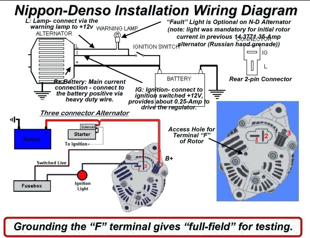
The "3-wire" designation refers to the three essential wires connected to the alternator, excluding the heavy gauge battery wire. These wires are:
- Battery Wire (B+): A heavy-gauge wire that connects directly to the battery's positive terminal, providing the main charging current. This is almost always a large gauge wire.
- Stator Wire (STA): Usually a smaller gauge wire than the B+ wire. The stator wire connects to the stator winding inside the alternator, and provides a voltage reference signal to the internal regulator, allowing the regulator to sense the alternator output voltage.
- Ignition Wire (FLD or IGN): This wire is connected to a circuit that is only energized when the ignition switch is in the "run" position. It provides power to the voltage regulator and tells the alternator when to start charging.
Symbols – Lines, Colors, and Icons
A wiring diagram uses standardized symbols to represent electrical components and connections. Here's a breakdown of common symbols:
- Lines: Represent wires. Thicker lines typically indicate larger gauge wires capable of carrying higher current.
- Color Coding: Wires are often color-coded to help identify their function. Common colors include red (power), black (ground), blue, green, yellow, and white. The key will be located on the diagram. Note that color coding can vary slightly between vehicle models and years.
- Alternator Symbol: Typically represented as a circle with the letter "A" inside or a stylized representation of an alternator.
- Battery Symbol: A series of long and short parallel lines, representing the battery's cells. The "+" sign indicates the positive terminal, and the "-" sign indicates the negative terminal.
- Voltage Regulator Symbol: Often represented as a rectangle or square with the letters "VR" or "REG" inside.
- Ground Symbol: A symbol that looks like a series of downward-pointing lines, indicating a connection to the vehicle's chassis, which serves as the common ground for the electrical system.
- Fuse Symbol: A zigzag line enclosed in a rectangle or a simple line break, representing a fuse that protects the circuit from overcurrent.
- Connector Symbol: Usually represented as interlocking shapes, indicating a point where wires can be connected or disconnected.
Important Note: Always refer to the specific wiring diagram for your vehicle. While the general principles are the same, the exact wiring configuration and color codes may vary depending on the year, make, and model.
How It Works
The Ford internal regulator 3-wire alternator system works as follows:
- When the ignition switch is turned to the "run" position, voltage is supplied to the Ignition Wire (FLD/IGN). This energizes the internal voltage regulator.
- The voltage regulator senses the battery voltage. If the battery voltage is below the desired charging voltage (e.g., 13.8-14.7 volts), the regulator allows current to flow through the alternator's rotor winding (also called the field winding).
- The rotating rotor creates a magnetic field. As the rotor spins, the magnetic field induces a current in the alternator's stator windings.
- The AC current generated by the stator is converted to DC current by a set of rectifier diodes inside the alternator.
- The DC current flows from the alternator, through the Battery Wire (B+), and to the battery, charging it.
- The voltage regulator constantly monitors the voltage at the Stator (STA) wire. As the battery voltage reaches the desired charging voltage, the regulator reduces the current flowing through the rotor winding, thereby reducing the alternator's output. This maintains a stable charging voltage, preventing overcharging the battery.
This closed-loop feedback system ensures that the battery is charged efficiently and safely, while also providing power to the vehicle's electrical accessories.
Real-World Use – Basic Troubleshooting Tips
Here are some common problems and how to troubleshoot them using the wiring diagram:
- Battery Not Charging:
- Check the B+ wire: Ensure the B+ wire is securely connected to the battery's positive terminal and that there are no breaks or corrosion. Use a multimeter to check for voltage at the B+ terminal on the alternator with the engine running. You should see battery voltage or slightly higher.
- Check the FLD/IGN wire: Verify that the FLD/IGN wire is receiving voltage when the ignition switch is in the "run" position. If not, check the fuse for that circuit.
- Check the STA wire: Use a multimeter to check for voltage on the STA wire.
- Check the alternator itself: If the wiring checks out, the alternator may be faulty. Have it tested at an auto parts store.
- Overcharging (Battery Boiling):
- Check the voltage regulator: The internal voltage regulator may be faulty. This usually requires replacing the entire alternator.
- Check for a faulty ground: A poor ground connection can cause the voltage regulator to malfunction.
- Charging System Warning Light:
- Check the bulb: Make sure the warning light bulb is not burned out.
- Check alternator output: Use a multimeter to check the alternator's output voltage. If it's significantly below the expected range, the alternator may be faulty.
When troubleshooting, always use a multimeter to check for voltage and continuity. A multimeter is an invaluable tool for diagnosing electrical problems. Also, visually inspect all wiring for damage, corrosion, or loose connections.
Safety – Highlight Risky Components
Working on electrical systems can be dangerous. Here are some safety precautions to follow:
- Disconnect the Battery: Always disconnect the negative battery cable before working on any electrical components. This prevents accidental short circuits and potential electric shock.
- Work in a Well-Ventilated Area: Battery acid can produce explosive hydrogen gas. Work in a well-ventilated area to avoid a build-up of gas.
- Use Insulated Tools: Use tools with insulated handles to protect yourself from electric shock.
- Be Careful Around the Alternator: The alternator can get very hot, especially after the engine has been running. Allow it to cool down before touching it.
- Avoid Short Circuits: Be careful not to create short circuits when working with electrical components. A short circuit can cause damage to the wiring, components, and even the battery.
- Handle Batteries with Care: Batteries contain corrosive acid. Avoid contact with skin and eyes. If contact occurs, flush immediately with water and seek medical attention.
Risk of Electric Shock: The charging system operates at 12 volts, which is generally considered safe. However, improper handling or short circuits can still create potentially dangerous situations. Always disconnect the battery and use caution when working on electrical components.
By understanding the Ford internal regulator 3-wire alternator wiring diagram and following these safety precautions, you can confidently tackle charging system repairs and modifications on your vehicle. Remember to always refer to the specific wiring diagram for your vehicle to ensure accuracy.
We have a printable version of the Ford Internal Regulator 3-Wire Alternator Wiring Diagram available for download. This detailed diagram will be a helpful resource when working on your vehicle's charging system. You can find the download link by contacting us directly.