
Ford Mustang Front Suspension Diagram
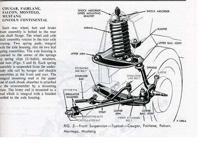
Understanding the front suspension of your Ford Mustang is crucial for various reasons, whether you're tackling routine maintenance, diagnosing a nagging issue, planning performance upgrades, or simply satisfying your mechanical curiosity. This article will dissect a typical Ford Mustang front suspension diagram, explaining its key components, functionality, and how it all works together. We aim to provide you, the experienced DIYer, with a clear and comprehensive guide, empowering you to work on your Mustang with greater confidence and understanding.
Purpose of a Ford Mustang Front Suspension Diagram
A front suspension diagram serves as a roadmap to understanding the complex interplay of parts in your Mustang's front end. It's not just a pretty picture; it's an essential tool for:
- Diagnosis: Pinpointing the source of suspension noises, uneven tire wear, or handling issues.
- Repair: Identifying the correct parts for replacement and understanding their location and orientation.
- Modification: Planning and executing performance upgrades, such as lowering springs, upgraded shocks, or sway bar enhancements.
- Learning: Gaining a deeper understanding of automotive engineering principles and how suspension systems work.
Having access to a detailed diagram can save you time and money by allowing you to accurately diagnose problems and avoid unnecessary repairs. It also ensures you're using the correct parts when making replacements or upgrades.
Key Specs and Main Parts (Fox Body Mustang Example)
Let's consider a simplified diagram of a 1979-1993 "Fox Body" Mustang's front suspension. This example uses a MacPherson strut design, common in many Mustangs throughout their history, although specific details will vary depending on the year and model.
Main Components:
- MacPherson Strut: A combined shock absorber and coil spring assembly. It provides damping and spring support for the vehicle. Key specs often include strut travel, spring rate (in lbs/in or N/mm), and overall strut length.
- Coil Spring: Located around the strut, it supports the weight of the vehicle and absorbs bumps. Spring rate is a critical specification.
- Spindle (or Steering Knuckle): Connects the strut to the lower control arm and houses the wheel bearing and hub. It's the pivotal point for steering.
- Lower Control Arm: A triangular arm connecting the spindle to the chassis. It controls wheel movement and helps maintain proper suspension geometry. Key specs include its length and mounting point locations.
- Sway Bar (or Anti-Roll Bar): A torsion spring connecting the left and right sides of the suspension. It reduces body roll during cornering. Its diameter and material stiffness are key specs.
- Sway Bar End Links: Connect the sway bar to the struts or lower control arms.
- Tie Rods (Inner and Outer): Connect the steering rack to the spindle, allowing you to steer the vehicle. Tie rod length and thread size are important for alignment.
- Steering Rack: The mechanical component that translates steering wheel input into lateral movement of the tie rods.
- Ball Joints: Allow for articulation between suspension components, specifically between the lower control arm and the spindle.
- Wheel Bearing and Hub: Allow the wheel to rotate smoothly on the spindle.
Symbols – Interpreting the Diagram
Suspension diagrams use a standardized set of symbols to represent different components and connections. Understanding these symbols is vital for accurate interpretation:
- Solid Lines: Typically represent rigid components like control arms, struts, and tie rods. The thickness of the line may indicate the component's relative size or stiffness.
- Dashed Lines: Often denote hidden components or lines of reference, like the centerline of the vehicle.
- Circles: Usually represent mounting points or pivot points (e.g., ball joints).
- Arrows: Indicate the direction of forces or movement, such as suspension travel or steering input.
- Color Coding (in some diagrams): May be used to differentiate between different types of components or systems (e.g., different colored lines for steering and suspension). Always refer to the diagram's legend for specific color meanings.
- Abbreviations: Expect to see abbreviations for materials (e.g., "AL" for aluminum, "ST" for steel) or component names (e.g., "LCA" for Lower Control Arm, "STR" for Strut).
How It Works
The front suspension of a Mustang, particularly a MacPherson strut design, operates through a series of interconnected movements. When the wheel encounters a bump:
- The wheel moves upward.
- This upward movement is transmitted through the spindle to the strut.
- The strut compresses, absorbing the energy of the bump through the coil spring and dampening it with the shock absorber.
- The lower control arm pivots, allowing for vertical wheel travel while maintaining proper suspension geometry.
- The sway bar resists body roll by transferring force from the compressed side of the suspension to the opposite side.
Simultaneously, the steering system allows the driver to control the direction of the wheels. Turning the steering wheel rotates the steering rack, which then moves the tie rods. The tie rods, in turn, pivot the spindles, steering the wheels left or right.
Real-World Use – Basic Troubleshooting Tips
Using the diagram, you can troubleshoot common suspension problems:
- Clunking Noises: Could indicate worn ball joints, loose sway bar end links, or a failing strut mount. Visually inspect these components for play or damage.
- Uneven Tire Wear: Often points to alignment issues caused by worn tie rod ends, ball joints, or damaged control arms. Refer to the diagram to check the condition and position of these parts.
- Excessive Body Roll: May be due to a worn sway bar or damaged sway bar end links. Check the sway bar's mounting points and the end links for any signs of wear or breakage.
- Bouncing: Suggests worn shocks. Inspect the struts for leaks or signs of reduced damping performance.
Remember to always compare your findings to the diagram to ensure you're correctly identifying the problematic component.
Safety – Handling Risky Components
Working on suspension components can be dangerous. Coil springs store a tremendous amount of energy and can cause serious injury if released improperly.
- Always use proper spring compressors when removing or installing coil springs. Make sure the compressor is securely attached and follow the manufacturer's instructions carefully.
- Never attempt to disassemble a strut without using a spring compressor.
- Loosen lug nuts before lifting the vehicle.
- Always use jack stands to support the vehicle after lifting it with a jack. Never work under a vehicle supported only by a jack.
- Wear safety glasses to protect your eyes from flying debris.
- If you're unsure about any procedure, consult a qualified mechanic.
Warning: Suspension work can affect your vehicle's handling and safety. It is strongly recommended to have your work inspected by a qualified mechanic and to have a wheel alignment performed after any suspension modifications or repairs.
We have a detailed front suspension diagram available for download. This diagram provides even more specific information about component locations, dimensions, and torque specifications. With this resource and the knowledge gained from this article, you'll be well-equipped to tackle many front suspension tasks on your Ford Mustang.