Ford Neutral Safety Switch Wiring Diagram
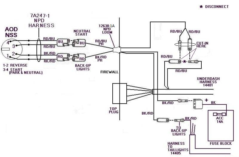
Alright, let's dive into the Ford Neutral Safety Switch wiring diagram. This document is your roadmap when dealing with starting and transmission-related issues on your Ford. Whether you're troubleshooting a no-start condition, installing an aftermarket alarm, or simply trying to understand the intricacies of your vehicle's electrical system, understanding this diagram is crucial. We've got the actual diagram file available for you to download at the end of this article, so you can follow along and refer to it later.
Why This Diagram Matters
This diagram isn't just a pretty picture; it's an essential tool for several reasons:
- Troubleshooting No-Start Conditions: The neutral safety switch is a primary suspect when your car won't start, especially if you hear a clicking sound. The diagram helps you trace the electrical path and pinpoint the fault.
- Transmission Issues: Problems with reverse lights, cruise control disengagement, or even shifting can sometimes be traced back to a faulty or misadjusted neutral safety switch. The diagram illuminates its role in these systems.
- Aftermarket Installations: Installing alarms, remote starters, or other electrical modifications often requires tapping into the ignition or transmission circuits. The diagram shows you exactly where to make those connections safely and correctly.
- Learning the System: Even if you're not facing immediate problems, understanding the diagram deepens your knowledge of your car's electrical system, making you a more confident and capable DIYer.
Key Specs and Main Parts
Before we dig into the lines and squiggles, let's identify the key components:
- Neutral Safety Switch (NSS) / Transmission Range Sensor (TRS): These terms are often used interchangeably, although some newer Fords use a dedicated TRS. This switch is physically mounted on the transmission and senses the gear selector position (Park, Reverse, Neutral, Drive, etc.). It allows the starter to engage *only* in Park or Neutral.
- Ignition Switch: The physical switch you turn with your key to start the engine.
- Starter Solenoid: A relay that provides high current to the starter motor. Sometimes located on the starter itself, other times mounted remotely.
- Starter Motor: The electric motor that cranks the engine.
- Fuse Box/Power Distribution Box: Houses fuses and relays that protect and control various circuits, including those related to the NSS.
- PCM (Powertrain Control Module)/ECM (Engine Control Module): The car's computer, which receives input from the NSS/TRS for various functions, including cruise control and transmission control.
- Reverse Lights: The lights at the rear of the vehicle that illuminate when in reverse. They are almost always wired through the NSS/TRS.
Key Specs: Voltage is almost always 12V DC in these circuits. Expect to see wire gauges ranging from 14 to 18 AWG, depending on the current draw of the components. The specific pinout of the NSS/TRS connector will vary by year and model, so always refer to the correct diagram for your vehicle.
Symbols: Deciphering the Diagram
Wiring diagrams use a standardized set of symbols to represent components and connections. Here's a breakdown of the common ones you'll see in the Ford NSS wiring diagram:
- Lines: Solid lines represent wires. Dashed lines might indicate shielded wires or connections within a module (like the PCM). Line thickness usually (but not always) reflects wire gauge/current carrying capacity.
- Colors: Wire colors are typically abbreviated (e.g., RD for Red, BLK for Black, YEL for Yellow, GRN for Green, WHT for White, BLU for Blue). Sometimes you'll see combinations like RD/WHT (Red with a White stripe). Wire colors are *extremely* important for tracing circuits.
- Circles/Dots: A solid circle indicates a wire splice. An open circle may represent a connector pin.
- Ground Symbol (⏚): Indicates a connection to the vehicle's chassis ground (typically the metal frame of the car).
- Resistors ( ⎍ ): Resistors limit current flow.
- Capacitors ( | | ): Capacitors store electrical energy.
- Diodes ( ▻| ): Diodes allow current to flow in only one direction.
- Relays ( ⎍□ ): Relays are electrically operated switches. The coil (represented by the resistor symbol) controls the switch contacts (represented by two lines that either connect or break).
- Switches ( ─/─ ): Represent mechanical switches that open or close a circuit (like the ignition switch or the NSS itself).
- Fuses ( ⌁ ): Fuses protect the circuit from overcurrent.
Pay close attention to the ground symbols. A good ground connection is *essential* for the NSS circuit to function properly. Corrosion or loose ground connections are common culprits in electrical problems.
How It Works: The Electrical Pathway
Here's a simplified explanation of how the neutral safety switch circuit typically works:
- Key On: When you turn the ignition key to the "Start" position, voltage is applied to the starter circuit.
- NSS Activation: The neutral safety switch, depending on its position (Park or Neutral), either *completes* or *interrupts* the circuit to the starter solenoid.
- Solenoid Engagement: If the NSS is in Park or Neutral, it allows voltage to pass through to the starter solenoid's control circuit. The solenoid then engages, connecting the battery's high-current positive terminal to the starter motor.
- Starter Motor Cranking: The starter motor spins, cranking the engine.
In addition to the starting function, the NSS/TRS also provides input to the PCM. The PCM uses this input to determine the gear selector position for functions like:
- Reverse Lights: When in Reverse, the NSS/TRS closes the circuit to the reverse lights.
- Cruise Control: The PCM may disengage cruise control if the transmission is shifted out of Drive.
- Transmission Control: The PCM uses the TRS signal for shift scheduling in automatic transmissions.
Real-World Use: Basic Troubleshooting Tips
Here are some common troubleshooting scenarios and how the wiring diagram can help:
- No Start, No Click: Use the diagram to check for voltage at the starter solenoid's control wire when the key is in the "Start" position. If there's no voltage, trace the circuit back through the NSS, ignition switch, and any relevant fuses or relays.
- No Start, Clicking Sound: The clicking sound indicates the starter solenoid is engaging but the starter motor isn't turning. This is less likely to be NSS related, and more likely a bad starter motor or a low battery voltage. However, use the diagram to verify the wiring to the starter is intact.
- Reverse Lights Not Working: With the transmission in Reverse, check for voltage at the reverse light bulbs. If there's no voltage, trace the circuit back through the NSS and any relevant fuses. A common problem is a misadjusted NSS that isn't properly closing the circuit when in Reverse.
- Cruise Control Issues: If cruise control disengages unexpectedly, the NSS/TRS signal to the PCM might be intermittent. Use a multimeter to check the continuity of the wires between the NSS/TRS and the PCM, referring to the diagram for pin locations.
When troubleshooting, always use a multimeter to check for voltage, continuity, and ground. A test light can also be helpful, but a multimeter provides more detailed information.
Safety: Highlighting Risky Components
Working with electrical systems can be dangerous. Keep these safety tips in mind:
- Disconnect the Battery: *Always* disconnect the negative battery terminal before working on any electrical circuits. This prevents accidental shorts and electrical shocks.
- High Current: The starter circuit carries a *very* high current. Be extremely cautious when working around the starter motor and solenoid.
- Airbags: On some vehicles, the NSS circuit may be near or integrated with airbag wiring. *Never* tamper with airbag wiring unless you are specifically trained and equipped to do so. Accidental airbag deployment can cause serious injury.
- Fuses are Your Friend: Never bypass fuses. They are designed to protect the circuit from overcurrent and prevent fires. If a fuse blows repeatedly, there's a problem in the circuit that needs to be addressed.
- Use the Right Tools: Use insulated tools designed for automotive electrical work.
Also, never test for shorts by directly connecting wires. This can damage components and create a fire hazard. Use a multimeter in continuity mode instead.
By understanding the Ford Neutral Safety Switch wiring diagram and following safe practices, you can effectively diagnose and repair electrical issues related to your vehicle's starting and transmission systems. We have the diagram file available for you. Now, you can download the wiring diagram to use it as a reference.