
Ford One Wire Alternator Wiring Diagram
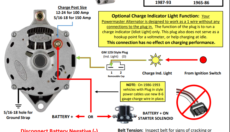
Alright, let's dive into the world of Ford one-wire alternator wiring diagrams. Whether you're retrofitting a classic Mustang, upgrading your charging system, or just trying to understand how your alternator works, knowing how to read and interpret these diagrams is crucial. We're going to break it down in a way that's both technically accurate and easy to understand, even if you're not an electrical engineer.
Purpose: Why You Need This Diagram
A Ford one-wire alternator wiring diagram is your roadmap to a functional charging system. It’s not just a nice-to-have; it’s often essential for several key scenarios:
- Retrofitting/Upgrading: Swapping out an old generator for a modern alternator, or upgrading to a higher amperage alternator, almost always requires modifying the wiring. A diagram shows you exactly where each wire needs to go.
- Troubleshooting: Is your battery not charging? Is the alternator light staying on? The diagram helps you trace the circuit, pinpoint faults (like broken wires or shorts), and test components systematically.
- Understanding the System: Even if everything's working fine, understanding the diagram gives you a deeper appreciation for how your car's electrical system functions. You'll know why things are wired the way they are.
- Custom Builds: For those tackling engine swaps or completely custom builds, you’re essentially starting from scratch. The diagram becomes your bible for the charging system.
Key Specs and Main Parts
Before we get to the diagram itself, let's cover the key players in a typical one-wire alternator setup:
- Alternator: The heart of the system. Its job is to convert mechanical energy from the engine into electrical energy to charge the battery and power the car's electrical components. Key specs include its amperage output (e.g., 60 amp, 100 amp) and whether it's internally regulated (which one-wire alternators always are).
- Battery: The energy reservoir. It stores electrical energy to start the engine and power accessories when the engine isn't running. Its specification is Voltage(12V).
- Main Power Wire (Charge Wire): This heavy-gauge wire connects the alternator's output terminal (usually marked with a "BAT" or "+" symbol) directly to the positive (+) terminal of the battery. Its gauge (thickness) is crucial. Too thin, and it can overheat and potentially cause a fire. Typically, 8-gauge or larger is recommended for most one-wire alternators.
- Ground Wire: Equally important as the power wire. It provides the return path for the electrical current. The alternator case needs to be securely grounded to the engine block or chassis. Again, use a heavy-gauge wire (same gauge as the charge wire).
- Fuse/Fusible Link (Optional but Recommended): Placed inline on the charge wire, close to the battery. It protects the system from overloads and short circuits. Its rating is determined based on the maximum current output.
Symbols: Decoding the Diagram
Wiring diagrams use standardized symbols to represent components and connections. Here's what you'll typically find on a Ford one-wire alternator diagram:
- Solid Lines: Represent wires. The thickness of the line often indicates the wire gauge (thicker line = heavier gauge wire).
- Dashed Lines: Often represent optional connections or grounding points.
- Alternator Symbol: A stylized representation of the alternator, usually with terminals labeled (e.g., "BAT" or "+").
- Battery Symbol: Two or more parallel lines of increasing length. "+" and "-" symbols indicate polarity.
- Ground Symbol: Usually looks like three horizontal lines getting progressively shorter, connected to a vertical line. Indicates a connection to the vehicle's chassis (ground).
- Fuse Symbol: A squiggly line inside a rectangle, or simply a rectangle with a line through it.
Color Coding: While not always consistent, wiring diagrams often use colors to identify wires. Common colors include:
- Red: Typically represents the main power wire from the alternator to the battery.
- Black: Usually indicates ground connections.
Important Note: Always refer to the specific legend or key provided with the diagram you're using, as color coding and symbols can vary slightly.
How It Works: A Simplified Explanation
The beauty of a one-wire alternator is its simplicity. Here's the basic flow of electricity:
- The engine turns the alternator's pulley via a belt.
- Inside the alternator, a spinning rotor creates an alternating current (AC).
- The alternator's internal rectifier converts the AC to direct current (DC), which is what your car's electrical system uses.
- The voltage regulator (also internal in a one-wire alternator) maintains a constant voltage output (typically around 14 volts).
- The DC current flows from the alternator's output terminal, through the main power wire, and directly to the battery's positive (+) terminal.
- The battery charges, and the excess electrical energy is used to power the car's lights, radio, and other accessories.
- The ground wire provides the return path for the current back to the alternator, completing the circuit.
The "one-wire" designation refers to the fact that only one wire (the main charge wire) is needed to connect the alternator to the battery. Unlike older alternators that required separate wires for sensing voltage and controlling the regulator, the one-wire alternator handles all that internally. It usually “self-excites” meaning that when the alternator reaches a certain RPM it begins to produce current.
Real-World Use: Basic Troubleshooting Tips
So, you've got a diagram, and you're ready to troubleshoot. Here are a few common problems and how the diagram can help:
- Battery Not Charging: Use a multimeter to check the voltage at the alternator's output terminal with the engine running. It should be around 14 volts. If it's significantly lower (e.g., 12 volts or less), the alternator may be faulty. Also, check the continuity of the main power wire and ground wire.
- Overcharging (Battery Boiling): This is less common with internally regulated alternators, but it can happen. Use a multimeter to check the voltage at the battery with the engine running. If it's significantly higher than 14.5 volts, the internal voltage regulator is likely bad.
- Blown Fuse/Fusible Link: Inspect the fuse or fusible link on the charge wire. If it's blown, it indicates an overcurrent situation, likely a short circuit. Trace the wiring to find the short before replacing the fuse.
- Voltage Drop: Use your multimeter to measure voltage drop along the main power wire. Excessive voltage drop (more than 0.5 volts) indicates a poor connection or a corroded wire.
Pro Tip: Always use a quality multimeter for electrical testing. A cheap multimeter can give inaccurate readings and lead you down the wrong path.
Safety: Respect the Electrons
Working with electrical systems can be dangerous. Keep these safety precautions in mind:
- Disconnect the Battery: Always disconnect the negative (-) battery terminal before working on the electrical system. This prevents accidental shorts and shocks.
- Insulated Tools: Use tools with insulated handles.
- Avoid Jewelry: Remove rings, watches, and other jewelry that could conduct electricity.
- Identify High-Risk Components: The alternator's output terminal and the main power wire carry significant current. Avoid touching these components with the engine running or while testing the system.
- Proper Wire Sizing: Using too small of a gauge wire can lead to overheating and fires. Always consult the alternator manufacturer's recommendations for wire size.
A faulty electrical system can be dangerous, potentially causing fires or damaging sensitive electronic components. If you're not comfortable working with electrical systems, it's best to consult a qualified mechanic.
We have a printable Ford one-wire alternator wiring diagram readily available for download. It includes the key components, color-coded wiring, and safety guidelines for easy reference.