Ford Ranger Air Conditioning Diagram
Alright folks, let's dive into the air conditioning system on your Ford Ranger. Understanding the AC system is crucial whether you're tackling a repair, planning an upgrade, or just want to know how your truck keeps you cool on those scorching days. This article will walk you through a typical Ford Ranger AC diagram, explaining the key components, how they work together, and how to interpret the diagram itself. We'll be focusing on the overall principles, so while there might be slight variations between model years, the fundamentals will remain the same.
Purpose of the Air Conditioning Diagram
Why bother understanding the AC diagram? Simple: it's your roadmap to diagnosing and fixing AC problems. A diagram allows you to:
- Troubleshoot: Identify where a problem might be originating by understanding the flow of refrigerant and the location of components.
- Repair: Accurately identify and replace faulty parts.
- Upgrade: Plan modifications or additions to the AC system, like adding an auxiliary condenser or upgrading the compressor.
- Understand: Gain a deeper understanding of how your vehicle's AC system functions.
Key Specs and Main Parts
Before we look at the diagram, let’s quickly cover the main components you'll find in a Ford Ranger's AC system:
- Compressor: The heart of the system. It compresses the refrigerant gas, raising its pressure and temperature. Usually belt-driven off the engine. Key spec: Displacement (cubic inches or cm3) – determines the amount of refrigerant compressed per revolution.
- Condenser: Located at the front of the vehicle (usually in front of the radiator). It's a heat exchanger that cools the high-pressure, high-temperature refrigerant gas, turning it into a high-pressure liquid.
- Receiver Drier (or Accumulator): This component acts as a filter and reservoir. It removes moisture and debris from the refrigerant and stores excess liquid refrigerant. The drier contains a desiccant that absorbs moisture.
- Expansion Valve (or Orifice Tube): This regulates the flow of refrigerant into the evaporator. It creates a pressure drop, causing the liquid refrigerant to expand and evaporate.
- Evaporator: Located inside the passenger compartment. It's another heat exchanger that absorbs heat from the cabin air, cooling it down. The low-pressure, low-temperature refrigerant boils and turns into a gas.
- Refrigerant Lines: These are the hoses and pipes that carry the refrigerant between the components. They are designed to withstand high pressures and temperatures.
- Pressure Switches: These monitor the refrigerant pressure within the system. They protect the compressor from damage if the pressure is too low or too high.
- Blend Door Actuator: Controls the mixing of hot and cold air to achieve the desired cabin temperature.
The refrigerant itself is the working fluid. Older Rangers may use R-12, but most modern systems use R-134a. Newer systems are transitioning to R-1234yf, which has a lower global warming potential.
Symbols – Understanding the Diagram
AC diagrams use standard symbols to represent components and lines. Here's a breakdown of common symbols:
- Lines: Solid lines typically represent refrigerant lines. Dotted lines may represent vacuum lines or electrical wiring. Line thickness can sometimes indicate the size of the line (larger diameter = thicker line).
- Arrows: Indicate the direction of refrigerant flow.
- Compressor: Usually depicted as a circle with a pump symbol inside.
- Condenser: Represented as a series of parallel lines (often wavy) with arrows showing airflow across them.
- Receiver Drier/Accumulator: Shown as a cylinder with different internal configurations depending on the type.
- Expansion Valve: Represented by a restriction symbol, often with a valve symbol.
- Evaporator: Similar to the condenser, but located inside the vehicle.
- Pressure Switches: Illustrated as switches with electrical contacts.
- Electrical Components: Relays, fuses, and control modules are depicted using standard electrical symbols.
Color coding isn't always consistent, but sometimes different colored lines are used to distinguish between high-pressure and low-pressure sides of the system. Pay attention to any legend provided with the specific diagram you are using.
How It Works
Let's walk through the basic refrigeration cycle as depicted on the diagram:
- The compressor compresses the refrigerant gas, increasing its pressure and temperature.
- The high-pressure, high-temperature refrigerant gas flows to the condenser. Here, it rejects heat to the outside air and condenses into a high-pressure liquid.
- The high-pressure liquid refrigerant flows to the receiver drier (or accumulator), where moisture and contaminants are removed.
- The refrigerant then flows through the expansion valve (or orifice tube). This creates a pressure drop, causing the liquid refrigerant to expand and vaporize.
- The low-pressure, low-temperature refrigerant flows to the evaporator. Here, it absorbs heat from the cabin air, cooling the air and turning into a low-pressure gas.
- The low-pressure gas returns to the compressor, and the cycle repeats.
The blend door controls the mixture of air flowing through the heater core and the evaporator core. The control module receives inputs from the temperature selector inside the cabin and directs the blend door actuator to position the blend door accordingly.
Real-World Use – Basic Troubleshooting Tips
Using the diagram, you can start to diagnose common AC problems:
- No Cold Air: Check the compressor clutch. If it's not engaging, check the fuse and relay. Also check the pressure switches; low refrigerant pressure can prevent the compressor from engaging. Use the diagram to locate these components.
- Weak Airflow: Check the blower motor and resistor. The diagram will show you the blower motor circuit and the location of the resistor.
- Intermittent Cooling: Could be a faulty pressure switch, a cycling clutch, or a leak in the system. Use the diagram to trace the electrical connections to the compressor clutch and pressure switches.
- Leaks: Look for oil stains around fittings and components. Refrigerant leaks often leave an oily residue. The diagram can help you pinpoint the location of fittings and connections.
Always use proper gauges and tools when working with the AC system. Don’t just guess; proper diagnosis prevents wasted time and money.
Safety – Highlight Risky Components
Refrigerant is dangerous! Never release refrigerant into the atmosphere. It's harmful to the environment and can cause frostbite. Always recover refrigerant using approved equipment before disconnecting any AC lines. High-pressure refrigerant can cause serious injury. Wear safety glasses and gloves when working on the system.
The compressor also contains high-speed moving parts and is driven by the engine. Ensure the engine is off and the key is removed before working near the compressor.
Remember, working on the AC system requires specialized knowledge and equipment. If you're not comfortable with any aspect of the repair, take your vehicle to a qualified technician.
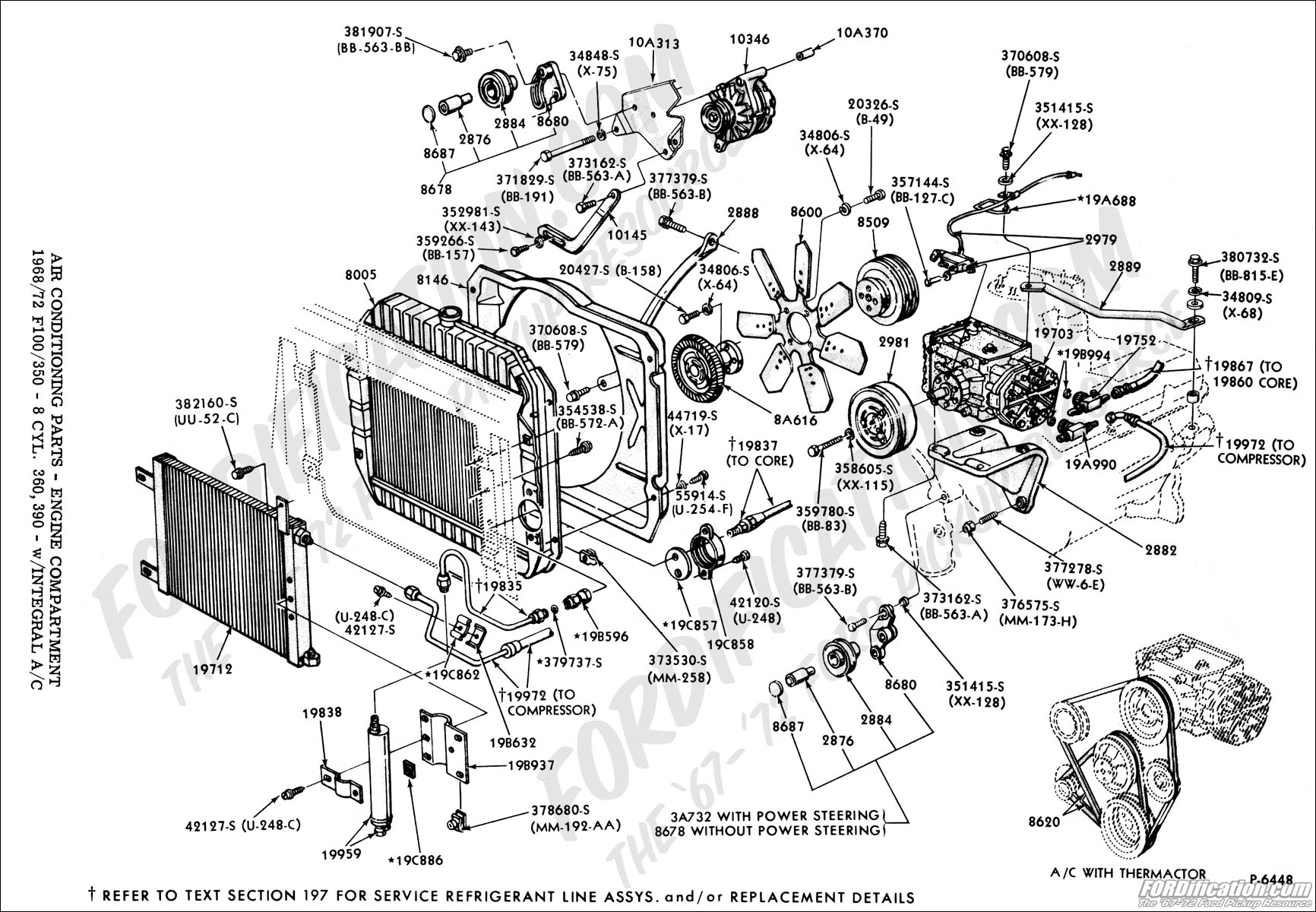
We have a sample Ford Ranger AC diagram available for download. This diagram provides a visual representation of the system and can be a valuable tool for troubleshooting and repair. Understanding this diagram is a great step towards maintaining and repairing your Ford Ranger's AC system.