Ford Ranger Fuel Pump Wiring Diagram
Understanding the Ford Ranger's fuel pump wiring diagram is crucial for various reasons, from simple repairs and diagnostics to more complex modifications and performance upgrades. Whether you're experiencing fuel delivery issues, planning to install an aftermarket fuel pump, or simply want to deepen your understanding of your vehicle's electrical system, this guide will provide you with the knowledge you need to navigate the fuel pump wiring. We'll break down the diagram, explain its components, and provide practical troubleshooting tips.
Purpose of Understanding the Fuel Pump Wiring Diagram
The fuel pump wiring diagram is essentially a roadmap of the electrical circuit that powers and controls the fuel pump. Its purpose is multifaceted:
- Diagnostics: When your Ranger exhibits symptoms like hard starting, stalling, or poor performance, the fuel pump is often a prime suspect. A wiring diagram allows you to trace the electrical path, identify potential breaks, shorts, or faulty components.
- Repair: Once you've identified a problem, the diagram guides you in repairing the wiring harness, replacing damaged connectors, or splicing in new wires correctly.
- Modification: Upgrading the fuel pump for performance enhancements often requires modifying the wiring. The diagram shows you where to tap into the circuit, add relays, or upgrade wire gauge to handle the increased current draw of a higher-flowing pump.
- Learning: Understanding the fuel pump circuit helps you grasp the fundamental principles of automotive electrical systems, empowering you to tackle other electrical issues on your Ranger.
Key Specs and Main Parts
The complexity of the fuel pump wiring can vary depending on the Ranger's year, engine, and options. However, some core components remain consistent:
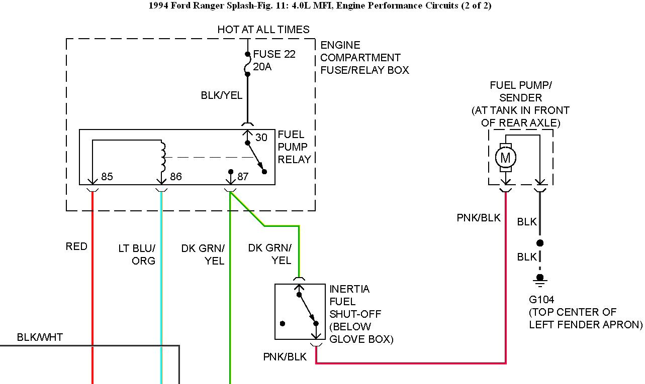
- Fuel Pump: Located inside the fuel tank, the electric fuel pump draws fuel from the tank and sends it to the engine. Its voltage requirement is typically 12V DC.
- Fuel Pump Relay: This electrically operated switch controls power to the fuel pump. It prevents the fuel pump from running continuously when the engine isn't running, improving safety and preventing damage.
- Inertia Switch (Fuel Cutoff Switch): This safety device interrupts power to the fuel pump in the event of a collision or sudden impact. It's designed to prevent fuel spillage and potential fires.
- PCM (Powertrain Control Module): The PCM is the vehicle's computer, and it controls the fuel pump relay based on engine speed, load, and other parameters.
- Fuel Pump Driver Module (FPDM): Some Ranger models (especially newer ones) use an FPDM to control the fuel pump speed. It allows the PCM to vary the fuel pump's output for improved fuel efficiency. The FPDM is usually located near the fuel tank.
- Wiring Harness: The network of wires that connects all these components.
- Fuses: Protective devices that prevent overcurrent from damaging the circuit.
- Ground Connections: Essential for completing the electrical circuit. A poor ground can cause numerous issues.
Symbols: Understanding the Diagram's Language
Fuel pump wiring diagrams use standardized symbols to represent electrical components and connections. Here's a breakdown of common symbols:
- Solid Lines: Represent wires. The thickness of the line *doesn't* necessarily indicate wire gauge.
- Dashed Lines: Often represent ground connections or shielded wires.
- Colors: Wires are color-coded, and the diagram will usually include a legend indicating what each color represents (e.g., RD=Red, BK=Black, WH=White, GN=Green, etc.).
- Relay Symbol: A rectangle or square with a coil symbol inside represents a relay. The coil energizes an electromagnet to switch a set of contacts.
- Fuse Symbol: Typically a zig-zag line within a rectangle.
- Ground Symbol: Usually a series of downward-pointing lines or a triangle connected to a horizontal line.
- Connector Symbol: Represented by a circle or a rectangle, indicating where wires are joined. Connector numbers are typically marked on the diagram.
Understanding these symbols is vital for accurately interpreting the wiring diagram.
How It Works: A Step-by-Step Explanation
Here's a simplified overview of how the Ford Ranger's fuel pump circuit typically functions:
- When you turn the ignition key to the "ON" position, the PCM sends a signal to the fuel pump relay.
- The fuel pump relay energizes, completing the circuit to the fuel pump.
- The fuel pump starts running, drawing fuel from the tank and pressurizing the fuel lines.
- The PCM monitors engine parameters (RPM, load, etc.) and adjusts the fuel pump speed via the FPDM (if equipped) to maintain optimal fuel pressure.
- If the inertia switch is tripped (due to an accident), it breaks the circuit to the fuel pump, shutting it off.
The exact sequence and components involved can vary depending on the specific Ranger model, but this provides a general understanding of the process.
Real-World Use: Basic Troubleshooting Tips
Here are some common troubleshooting scenarios and how the wiring diagram can help:
- Fuel Pump Not Running: Use a multimeter to check for voltage at the fuel pump connector. If there's no voltage, trace the circuit back to the fuel pump relay, inertia switch, and PCM. Check the fuel pump fuse. A blown fuse indicates a short circuit.
- Fuel Pump Runs Constantly: This could be a stuck fuel pump relay or a faulty PCM. The wiring diagram helps you locate the relay and identify the PCM control wire.
- Low Fuel Pressure: This could be a failing fuel pump, a clogged fuel filter, or a problem with the fuel pressure regulator. However, the wiring diagram can help you rule out electrical issues, such as a voltage drop to the fuel pump or a faulty FPDM (if equipped). Check ground connections for corrosion.
Remember to always start with the simplest checks first (fuse, relay) before moving on to more complex components.
Safety: Handling Risky Components
Working on the fuel pump circuit involves inherent risks:
- Fuel Vapors: Gasoline fumes are flammable and explosive. Always work in a well-ventilated area, and avoid sparks or open flames.
- Electrical Shock: Disconnect the negative battery cable before working on any electrical components. The fuel pump circuit carries 12V, which can be dangerous under certain circumstances.
- Fuel Spillage: Be prepared for fuel spillage when disconnecting fuel lines. Have rags and a container ready to catch any fuel that leaks out.
Always prioritize safety when working on your vehicle's fuel system. If you're not comfortable with electrical work or handling fuel, it's best to consult a qualified mechanic.
This guide provides a solid foundation for understanding the Ford Ranger fuel pump wiring diagram. We have access to a detailed diagram file that matches your specific Ranger model. Knowing how to interpret this diagram will prove invaluable in diagnosing and repairing fuel delivery issues. Good luck with your projects!