Ford Ranger Tail Light Wiring Diagram
So, you're tackling the tail lights on your Ford Ranger, huh? Whether you're troubleshooting a faulty bulb, adding a custom light bar, or just plain curious about how the whole system works, understanding the tail light wiring diagram is absolutely crucial. This isn't just about randomly poking around with a multimeter; it’s about understanding the intricate dance of electricity that keeps you safe and legal on the road.
Why Bother with the Diagram?
Let's be honest, electrical gremlins are among the most frustrating to chase down in any vehicle. A tail light wiring diagram gives you a roadmap, a precise schematic to navigate the circuit. Specifically, having the diagram helps you:
- Diagnose problems quickly: Identify shorts, open circuits, or faulty grounds without guesswork.
- Perform repairs confidently: Replace damaged wires or connectors with the correct gauge and connection type.
- Install accessories safely: Add trailer wiring, auxiliary lights, or aftermarket tail lights without frying your electrical system.
- Understand the system: Knowing how the lights work will enable you to better understand your vehicle.
Key Specs and Main Parts of Ranger Tail Light Wiring
The specifics will vary slightly depending on the year and trim level of your Ranger, but the fundamental principles remain the same. Here’s a breakdown of the essential components and what to look for:
Core Components:
- Power Source (Battery): Everything starts here, providing the 12V DC needed to illuminate the lights.
- Fuses: Critical safety devices that protect the circuit from overloads. A blown fuse is often the first clue to a problem. Typically located in the engine bay fuse box and/or under the dashboard.
- Switch (Headlight Switch): Controls the activation of the tail lights, often linked to the headlights.
- Wiring Harness: The network of wires that connects all the components. Keep an eye out for damaged insulation or corroded connectors.
- Ground Connection: Provides a return path for the current to the battery. Poor grounds are a common cause of lighting issues. Usually bolted to the frame or body of the truck.
- Bulbs/LEDs: The light-emitting elements. Bulbs are generally incandescent or halogen, while newer Rangers often feature LEDs, offering longer life and lower power consumption.
- Sockets/Connectors: Hold the bulbs and provide electrical contact. Corroded or damaged sockets are a common issue.
Specific Light Functions:
- Tail Lights: Illuminate when the headlights are on, indicating the vehicle's presence.
- Brake Lights: Activate when the brake pedal is pressed, warning drivers behind you.
- Turn Signals: Indicate intended direction of travel.
- Reverse Lights: Illuminate when the vehicle is in reverse gear.
Wire Gauges: You'll typically find 18-gauge or 16-gauge wires used in tail light circuits. For higher-current applications, like brake lights, 16-gauge is generally preferred. Always replace damaged wires with the same gauge or a slightly larger one to maintain proper current carrying capacity.
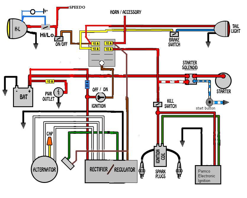
Decoding the Tail Light Wiring Diagram: Symbols, Lines, and Colors
The wiring diagram is a symbolic representation of the circuit. Understanding these symbols is key to deciphering its meaning.
- Solid Lines: Represent wires. Thicker lines usually indicate wires carrying more current.
- Dashed Lines: Often indicate a shielded cable, a ground wire, or a less critical connection.
- Color Codes: Extremely important! Each wire is color-coded according to a standard. The diagram will include a legend that translates each color to its function (e.g., Brown = Tail Lights, Green = Right Turn, Yellow = Left Turn, White = Ground). Common colors on a Ford Ranger often include:
- White: Ground
- Brown: Tail Lights
- Green: Right Turn/Brake
- Yellow: Left Turn/Brake
- Black: Power Source
- Symbols:
- Resistors: Zigzag line.
- Capacitors: Two parallel lines.
- Diodes: Triangle pointing to a line. (Often used in LED circuits)
- Ground: Series of lines decreasing in size, resembling an inverted Christmas tree.
- Fuse: A squiggly line inside a circle or rectangle.
- Switches: A break in the line with an arrow connecting to another point.
Connectors: Diagrams often use simplified symbols to represent connectors, sometimes with a number indicating the number of pins.
How the Tail Light Circuit Works: A Simplified Explanation
Let's break down how the typical tail light circuit functions:
- Power Flow: Power from the battery flows through a fuse to protect the circuit.
- Headlight Switch Activation: When you turn on the headlights, the headlight switch completes the circuit to the tail lights, causing them to illuminate.
- Brake Light Activation: When you press the brake pedal, a separate switch activates, sending power to the brake light filaments (or LEDs). Importantly, the brake lights often share the same bulb as the turn signals (dual filament bulb), with the brake light signal overriding the turn signal when both are activated.
- Turn Signal Activation: When you engage the turn signal, the flasher unit (a timer circuit) sends intermittent pulses of power to the appropriate turn signal bulb.
- Grounding: The current flows through the bulb filament (or LEDs) and then returns to the battery through the ground connection.
Real-World Troubleshooting: Common Problems and Fixes
Okay, so you have the diagram, now what? Here are some common problems you might encounter and how to use the diagram to diagnose them:
- No Tail Lights: Check the tail light fuse first. If it's blown, replace it. If it blows again immediately, you have a short circuit. Use the diagram to trace the circuit and look for damaged wires. If the fuse is good, test the headlight switch.
- One Tail Light Out: Start by replacing the bulb. If that doesn't fix it, check the socket for corrosion. Use a multimeter to test for voltage at the socket. If there's no voltage, trace the wiring back to the headlight switch, checking for breaks or loose connections.
- Brake Lights Not Working: Check the brake light fuse. If it's good, test the brake light switch located near the brake pedal. Use a multimeter to see if the switch is sending power when the pedal is pressed.
- Turn Signals Not Working: Check the flasher unit. If the turn signals flash too fast, it often indicates a burned-out bulb on one side.
Multimeter is Your Friend: A multimeter is essential for electrical troubleshooting. Use it to test for voltage, continuity (a closed circuit), and resistance. Learn how to use it properly before attempting any electrical repairs.
Safety First: Electrical Precautions
Working with automotive electrical systems can be dangerous. Here are some crucial safety precautions:
- Disconnect the Battery: Always disconnect the negative battery terminal before working on any electrical circuits. This prevents accidental shorts and shocks.
- Use Proper Tools: Use insulated tools designed for electrical work.
- Wear Safety Glasses: Protect your eyes from sparks or debris.
- Be Careful with Airbags: Airbag circuits contain capacitors that can store a charge even after the battery is disconnected. Consult a service manual for proper airbag deactivation procedures. Never probe or cut airbag wiring unless you are trained to do so.
- Don't Work in Wet Conditions: Water conducts electricity. Avoid working on electrical systems in damp or wet environments.
Working on your Ford Ranger's electrical system can be rewarding, but always prioritize safety. If you're uncomfortable with any of these procedures, it's best to consult a qualified mechanic.
Remember, this article is intended as a general guide. Always consult the specific wiring diagram for your particular Ford Ranger year and model for accurate information. And remember, we have the file, and you can download the diagram for your specific year and model to have the exact blueprint you need for your project!