
Ford Ranger Tail Light Wiring Harness
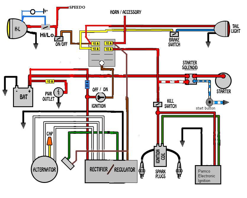
The tail light wiring harness on your Ford Ranger is a critical component, responsible for illuminating your brake lights, turn signals, and running lights. Understanding its wiring diagram isn't just an academic exercise; it's essential for properly diagnosing and repairing electrical issues, installing aftermarket accessories, or even performing a full tail light assembly replacement. This guide will provide an in-depth look at the Ford Ranger tail light wiring harness, helping you confidently navigate its intricacies. We'll assume you have a good working knowledge of basic automotive tools and safe electrical practices.
Why Understanding the Tail Light Wiring Harness Matters
Knowing how your Ford Ranger's tail light wiring is configured is vital for several reasons:
- Troubleshooting Electrical Problems: A malfunctioning tail light can be caused by a blown bulb, a corroded connection, or a break in the wiring. A wiring diagram allows you to systematically trace the circuit and pinpoint the fault.
- Installing Aftermarket Accessories: If you plan on adding a trailer hitch with wiring, installing an upgraded tail light assembly, or adding custom lighting, you'll need to understand the existing wiring to ensure compatibility and avoid damaging your truck's electrical system.
- Performing Repairs: Accidents happen. If your tail light assembly is damaged, knowing the wiring layout is critical for splicing wires correctly and ensuring all functions are restored.
- Enhancing Your Knowledge: Even if you don't currently have any issues, understanding how your vehicle's electrical system works empowers you to perform basic maintenance and preventative checks, potentially saving you money and time in the long run.
Key Specs and Main Parts of the Tail Light Wiring Harness
The Ford Ranger tail light wiring harness isn't a single, monolithic entity. It's a collection of wires, connectors, and terminals working in concert. Here’s a breakdown of the key components:
- Wiring: The harness consists of multiple wires of varying gauges (thickness) and colors. The gauge of the wire determines its current-carrying capacity. Common gauges in tail light harnesses include 16-gauge and 18-gauge. Each wire is insulated to prevent short circuits.
- Connectors: These are the plastic housings that plug into the tail light assembly and the main vehicle wiring harness. They provide a secure and weatherproof connection. Pay attention to the pinout of each connector – this specifies which wire connects to which terminal within the connector.
- Terminals: These are the metal contacts inside the connectors that make the electrical connection. They can be crimped onto the wires or permanently attached. Corrosion on terminals is a common cause of tail light malfunctions.
- Ground Point(s): The tail lights need a good ground connection to complete the circuit. This is typically achieved by connecting a wire from the harness to the vehicle's frame. A poor ground connection can cause erratic behavior or dim lights.
- Sockets: These are the receptacles that hold the light bulbs themselves. They need to be clean and free of corrosion for proper bulb operation.
Understanding Wiring Diagram Symbols
Wiring diagrams use standardized symbols to represent various components. Here's a quick guide to some common symbols you'll encounter in a Ford Ranger tail light wiring diagram:
- Lines: Solid lines represent wires. Dotted lines may represent shielded cables or wires that are part of a sub-circuit. The thickness of the line does not necessarily indicate the wire gauge.
- Colors: Each wire is identified by a color code (e.g., BK for Black, RD for Red, YL for Yellow). These codes are usually printed directly on the wire.
- Circles/Dots: These typically indicate connection points, either splices or terminals within a connector.
- Rectangles/Squares: These can represent various components, such as relays, fuses, or control modules.
- Ground Symbol: This looks like an inverted Christmas tree and represents a connection to the vehicle's chassis (ground).
- Lamp Symbol: This represents the light bulb itself.
- Connector Symbol: Typically a series of small squares or rectangles connected by a line, representing the physical connector. Numbers next to the connector symbol often indicate the pin number.
When reading a wiring diagram, it's crucial to pay attention to the wire colors and the component symbols. Trace the circuit from the power source (e.g., the battery or a fuse) to the tail light bulb, noting all the components in between. This will help you understand the flow of electricity and identify potential problem areas.
How the Tail Light Wiring System Works
The tail light wiring system is relatively straightforward. Here's a simplified explanation of how it works:
- Power Source: Power is supplied to the tail light circuit from the vehicle's battery, often through a fuse in the fuse box. The fuse protects the circuit from overloads.
- Switch Activation: The headlights and brake lights are activated by switches (the headlight switch on the dash and the brake light switch on the brake pedal). The turn signals are activated by the turn signal switch on the steering column.
- Wiring Harness Distribution: When a switch is activated, it sends power through the wiring harness to the appropriate tail light bulbs.
- Ground Connection: The electricity flows through the bulb's filament, causing it to illuminate. The circuit is completed when the electricity flows back to the battery through the ground connection.
The brake lights are typically wired separately from the running lights and turn signals. This is because the brake lights need to be brighter and more responsive. The turn signals are often controlled by a flasher module, which causes the lights to blink on and off.
Real-World Use: Basic Troubleshooting Tips
Here are some common tail light problems and how to troubleshoot them using your knowledge of the wiring harness:
- No Tail Lights: Check the fuse first. If the fuse is blown, replace it with a fuse of the same amperage. If the fuse blows again immediately, there's likely a short circuit in the wiring. Use a multimeter to check for continuity between the wires and ground.
- One Tail Light Out: Start by checking the bulb. If the bulb is good, check the socket for corrosion. Clean the socket with a wire brush and electrical contact cleaner. If that doesn't work, trace the wiring from the socket back to the connector and look for breaks or loose connections.
- Dim Tail Lights: This is often caused by a poor ground connection. Clean the ground connection point with a wire brush and make sure it's securely attached to the vehicle's frame.
- Turn Signal Not Working: Check the turn signal bulb first. If the bulb is good, check the flasher module. The flasher module is typically located under the dashboard.
- Brake Lights Not Working: Check the brake light switch, which is located on the brake pedal assembly. Also, check the brake light fuse.
Remember to always disconnect the battery before working on any electrical components. Use a multimeter to test for voltage and continuity. And always double-check your work before reconnecting the battery.
Safety Precautions
Working with automotive electrical systems can be dangerous. Always follow these safety precautions:
- Disconnect the Battery: This is the most important safety precaution. Disconnecting the battery prevents accidental shocks and short circuits.
- Wear Safety Glasses: Protect your eyes from sparks and debris.
- Use Insulated Tools: Use tools with insulated handles to prevent electrical shock.
- Work in a Well-Ventilated Area: Some electrical components may emit harmful fumes.
- Be Careful with Wires: Avoid cutting or damaging wires unnecessarily. If you need to splice wires, use proper crimping tools and connectors.
- Identify Live Wires: Use a multimeter to identify live wires before touching them.
- Avoid Water: Never work on electrical systems in wet conditions.
Warning: The vehicle's electrical system contains components that can store electrical energy, even after the battery is disconnected. Exercise caution when working around these components, such as the ignition system and the airbag system. Improper handling of these components can result in serious injury.
With a solid understanding of the Ford Ranger tail light wiring harness, you'll be better equipped to diagnose and repair electrical issues, install aftermarket accessories, and maintain your vehicle's lighting system. Always refer to the specific wiring diagram for your Ranger's year and model, as wiring configurations can vary.
We have the Ford Ranger Tail Light Wiring Diagram file available for download. This detailed diagram will provide even more clarity and specific information for your vehicle's electrical system. Understanding the wiring harness is critical for any repair. This file will empower you to approach electrical repairs with confidence and precision.