Ford Simple 3 Wire Alternator Wiring Diagram
Alright, let's dive into the Ford "Simple" 3-Wire Alternator Wiring Diagram. This setup is incredibly common on older Fords, and even some newer applications still retain its basic principles. Understanding this diagram is invaluable whether you're chasing down a charging problem, swapping an engine, or simply want to better understand your vehicle's electrical system. We're going to approach this like I'm standing beside you in the garage, pointing things out in a way that makes sense.
Purpose of Understanding the 3-Wire Diagram
Why bother learning this? Because it's the key to:
- Troubleshooting Charging Issues: Diagnosing why your battery isn't charging or is overcharging.
- Engine Swaps: Ensuring the alternator is correctly wired when installing a new engine (especially if it's not a direct replacement).
- Upgrades: Understanding how to upgrade to a higher-output alternator if your electrical needs have increased.
- Basic Electrical Understanding: It's a fundamental building block for understanding automotive electrical systems.
Without this knowledge, you're essentially stabbing in the dark when dealing with charging problems. A few minutes studying this diagram can save you hours of frustration (and a lot of money on unnecessary parts).
Key Specs and Main Parts
The "Simple" 3-Wire alternator gets its name from the fact that it needs only three wires to function. Let's break down the components:
- Alternator: The heart of the charging system. It converts mechanical energy from the engine into electrical energy. Key spec: Output amperage (e.g., 60A, 100A, etc.). Higher amperage alternators can support more electrical load (lights, stereo, etc.)
- Battery: Stores electrical energy and provides it to the starter and other components when the engine isn't running. Key spec: Cold Cranking Amps (CCA).
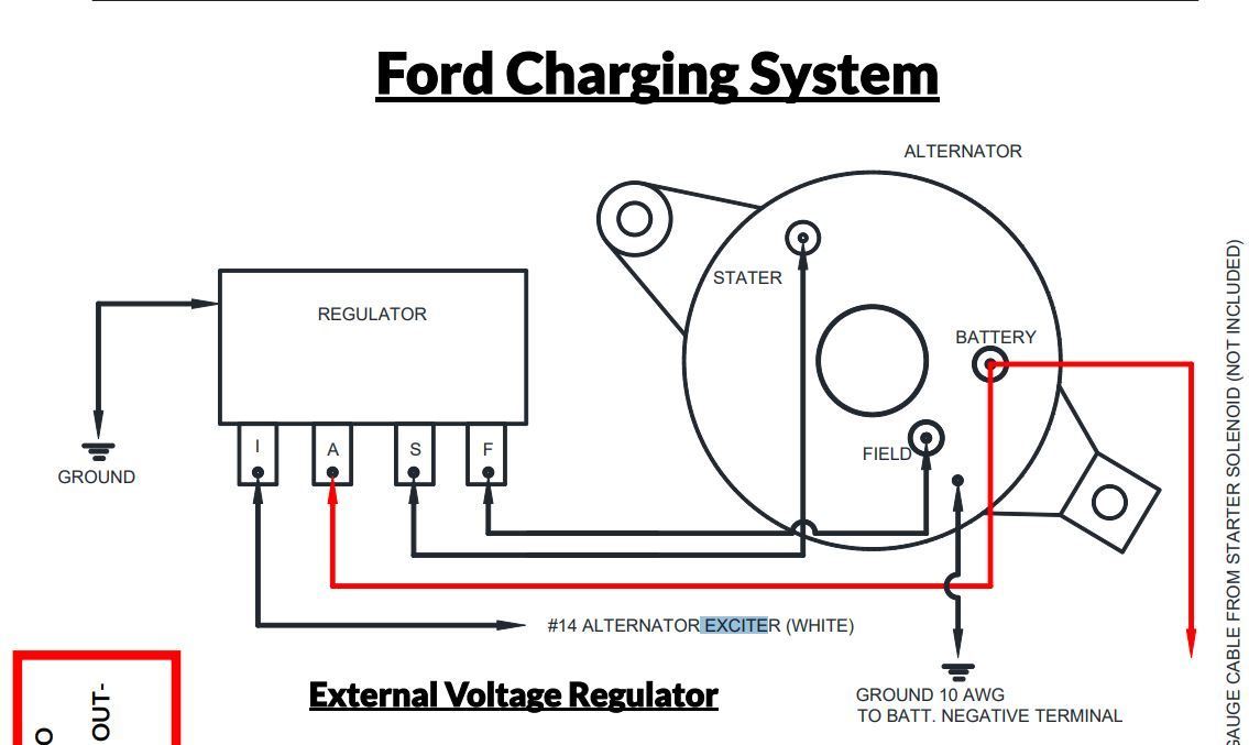
- Voltage Regulator: Controls the alternator's output voltage to prevent overcharging the battery. It's often (but not always) integrated into the alternator itself. This article covers both integrated and external voltage regulators.
- Battery Indicator Light (idiot light): Located on your dashboard, it illuminates when the alternator isn't charging correctly.
- Wiring Harness: The bundle of wires that connect all the components. Key spec: Wire gauge (thickness). Too small of a gauge wire can cause voltage drop and overheating.
- Fuses/Fusible Links: Safety devices that protect the electrical system from overcurrent. They're designed to blow (break the circuit) if too much current flows through them.
The three essential wires are usually (but not always, so check your vehicle's specific wiring diagram):
- Battery Terminal (BAT or B+): A heavy-gauge wire that carries the alternator's output directly to the battery. This is the main charging wire.
- Stator Wire (STA or S): This wire leads to the stator terminal on the alternator. It's mainly used to tell the vehicle's ECU (if equipped) about the engine's running condition. It sometimes is used on the idiot light circuit.
- Ignition Wire (IGN or I): A smaller-gauge wire that provides a 12V signal from the ignition switch to "excite" the alternator and tell it to start charging. This is what initially starts the charging process when you turn the key.
Symbols and Wire Colors
Understanding the symbols and color codes used in wiring diagrams is essential. Here are some common ones:
- Solid Line: Represents a wire.
- Dashed Line: Often indicates a wire that's part of a harness or a ground connection.
- Circle with a line through it: Represents a connection to ground (the chassis or body of the vehicle).
- Rectangle: Can represent a relay, switch, or fuse box.
- Zigzag Line: Represents a resistor.
- M: Usually stands for motor or module.
Wire colors vary, but some common conventions include:
- Red: Usually indicates a power wire (positive voltage).
- Black: Usually indicates a ground wire (negative voltage).
- Yellow: Often used for accessory circuits or ignition-switched power.
- Blue: Can be used for various circuits, often lighting or signals.
- Green: Sometimes used for grounds, or sensor signals.
Important: Always refer to your vehicle's specific wiring diagram to confirm wire colors and functions. Don't assume anything based solely on color.
How It Works – The Charging Process
Here's the basic sequence of events:
- Turning the Key: When you turn the ignition key to the "ON" position, the ignition wire (IGN/I) receives 12V. This voltage signal travels to the voltage regulator (either internal or external).
- Excitation: The voltage regulator uses this signal to "excite" the alternator's field windings. This creates a magnetic field inside the alternator.
- Rotation and Current Generation: When the engine starts and the alternator pulley spins, the magnetic field created by the field windings interacts with the stator windings. This generates alternating current (AC) electricity.
- Rectification: The AC electricity is then converted to direct current (DC) by a set of diodes within the alternator.
- Voltage Regulation: The voltage regulator monitors the battery voltage and adjusts the current flowing through the field windings to maintain a stable output voltage (typically around 13.8-14.4V). If the battery is low, the regulator increases the field current, causing the alternator to produce more output. If the battery is fully charged, the regulator reduces the field current.
- Charging the Battery: The DC electricity flows through the heavy-gauge battery wire (BAT/B+) to the battery, recharging it and providing power to the vehicle's electrical system.
The stator wire's (STA/S) purpose is, as said earlier, is mainly for telling the ECU what the engine is doing and can sometimes be part of the idiot light circuit.
That "idiot light" is important because it acts as a resistor, helping the alternator to initially energize (or "excite") itself. If the bulb is blown, the alternator might not charge.
Real-World Use – Basic Troubleshooting
Here are some common problems and how the 3-wire diagram can help you diagnose them:
- Battery Light Stays On: Could indicate a faulty alternator, a broken wire, a blown fuse, or a problem with the voltage regulator. Use a multimeter to check the voltage at the battery with the engine running. It should be between 13.8 and 14.4V. If it's significantly lower or higher, suspect the alternator or voltage regulator.
- Battery Not Charging: Check the battery wire (BAT/B+) for continuity (using a multimeter). Make sure it's properly connected at both ends. Also, check the ignition wire (IGN/I) for 12V with the ignition on. If you don't have voltage on the Ignition wire, trace back to the ignition switch, looking for broken wires or bad connections.
- Overcharging: Indicates a faulty voltage regulator. This can boil the battery dry and damage electrical components. Replace the voltage regulator (or the entire alternator if the regulator is integrated).
- Alternator Whining: This could be a sign of worn-out bearings or a failing diode. Replacing the alternator is usually the best option.
Pro Tip: Before condemning the alternator, check the belt tension. A loose belt can cause the alternator to slip, resulting in poor charging performance.
Safety Considerations
Working with automotive electrical systems can be dangerous. Keep these points in mind:
- Disconnect the Battery: Always disconnect the negative battery terminal before working on the electrical system. This prevents accidental shorts and potential electrical shocks.
- High Current: The battery wire (BAT/B+) carries high current. Be careful not to short it to ground. Use insulated tools and wear safety glasses.
- Battery Acid: Battery acid is corrosive. Wear gloves and eye protection when working near the battery.
- Moving Parts: Keep hands and clothing away from moving parts (like the alternator pulley and belt) when the engine is running.
Specifically, the positive terminal of the alternator (BAT/B+) is always "hot" (connected directly to the battery). A short circuit here can cause a fire or explosion.
Understanding the Ford 3-Wire Alternator Wiring Diagram is a powerful skill. It enables you to diagnose and repair charging problems, perform engine swaps with confidence, and upgrade your electrical system as needed. Take your time, be careful, and always refer to your vehicle's specific wiring diagram for accurate information.
And remember, we have a detailed, downloadable PDF version of the 3-Wire Alternator Wiring Diagram ready for you to use as a handy reference in your garage. This diagram will provide a visual aid to complement the information discussed in this article.