Ford Starter Solenoid Wiring Diagram
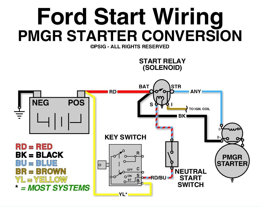
Understanding your Ford starter solenoid wiring diagram is crucial for a variety of reasons, whether you're tackling basic repairs, upgrading your electrical system, or simply want to understand how your car ticks. This article will break down the diagram, explain its components, and give you the knowledge to diagnose and fix common starter issues. Think of this as your guide to becoming more confident under the hood.
Why Bother with the Diagram?
The starter solenoid wiring diagram isn't just a pretty picture; it's your roadmap for navigating the electrical system responsible for starting your Ford. It's invaluable for:
- Troubleshooting Starting Problems: Is your car clicking but not starting? The diagram helps you pinpoint the source.
- Performing Electrical Repairs: Replacing a faulty solenoid or wiring? The diagram guides you through the process.
- Upgrading Your System: Installing a new battery, alternator, or starter? Ensure proper compatibility with the existing wiring using the diagram.
- General Understanding: Knowing how your car starts empowers you to maintain it and diagnose issues proactively.
Key Specs and Main Parts
Before diving into the diagram, let's identify the key components and their roles. Understanding these parts makes the diagram much easier to interpret:
- Battery: The heart of the system, providing the necessary electrical power. Common specs are 12V DC (Direct Current).
- Ignition Switch: Your key activates this switch, signaling the starter system to engage.
- Starter Solenoid: An electromagnetic switch that acts as a relay. It receives a small current from the ignition switch and uses it to control a much larger current flow to the starter motor. Key Specs: Voltage rating (usually 12V), Ampere rating (determines its switching capacity).
- Starter Motor: The muscle that physically cranks the engine. It requires a high current to operate. Key specs: Horsepower (HP), Voltage, and Number of teeth of the pinion gear.
- Ground Connections: Essential for completing the electrical circuit. Look for grounding straps or wires connecting to the chassis or engine block.
- Fuses and Relays: Protective devices to prevent overloads and manage electrical flow.
Decoding the Diagram: Symbols, Lines, and Colors
The wiring diagram uses a standardized set of symbols to represent components and connections. Let's break down the common elements:
- Lines: Lines represent wires. Thicker lines often indicate wires carrying higher currents. Dotted lines can indicate a control signal or a connection on the back of a component.
- Colors: Wires are color-coded for easy identification. Common colors include Red (positive battery), Black (ground), Yellow (ignition switch), and Blue or Green (starter signal). Always refer to the diagram's legend for the specific color codes for your model.
- Symbols:
- Battery: Represented by a series of long and short parallel lines.
- Solenoid: Often depicted as a coil symbol with switch contacts.
- Starter Motor: A circle with an "M" inside, sometimes with a gear symbol.
- Ground: Three horizontal lines decreasing in length, resembling an upside-down pyramid.
- Fuse: A zig-zag line enclosed in a rectangle.
- Relay: A coil symbol with associated switch contacts, similar to the solenoid but typically smaller.
- Switch: A line connecting to a point that can be opened or closed.
- Numbers/Labels: Each wire and component is often labeled with a number or code, referencing its function or location in the circuit.
Understanding these visual cues is essential to interpreting the flow of electricity through the starter system. The legend on the diagram is your key to unlocking specific symbols and color codes.
How It Works: The Starter System's Dance
Here's a step-by-step breakdown of how the starter system operates, referencing the wiring diagram:
- Key Ignition: You turn the key to the "Start" position. This closes the ignition switch, sending a low-current signal to the starter solenoid.
- Solenoid Activation: The solenoid receives the signal from the ignition switch. The solenoid coil energizes, creating a magnetic field. This field pulls a plunger (a metallic core) inside the solenoid.
- High Current Flow: The plunger, when pulled, closes a set of heavy-duty contacts inside the solenoid. This connects the battery's positive terminal directly to the starter motor.
- Starter Engagement: The starter motor receives a massive surge of electrical current. This current spins the motor, which engages a small gear (the pinion gear) with the engine's flywheel (or flexplate in automatic transmissions). The spinning gear then cranks the engine.
- Engine Start: Once the engine starts, you release the key, which opens the ignition switch. This de-energizes the solenoid, disconnecting the starter motor. The starter motor disengages from the flywheel to prevent damage.
The solenoid acts as an intermediary, allowing a small current from the ignition switch to control a very large current needed by the starter motor. This protects the ignition switch from being overwhelmed by the high current draw.
Real-World Use: Basic Troubleshooting Tips
Here are a few common starter system issues and how the wiring diagram can help:
- Clicking Sound, No Start: This often indicates a weak battery, poor connection, or a faulty solenoid. Check battery voltage, clean battery terminals, and use the diagram to trace the solenoid wiring for loose connections. If the battery and connections are good, the solenoid may be faulty and require replacement.
- No Sound, No Start: Check the ignition switch wiring using the diagram. A broken wire or faulty switch could prevent the signal from reaching the solenoid. Also, check the starter motor itself; it may be internally damaged.
- Starter Stays Engaged: A stuck solenoid or a faulty ignition switch could be the culprit. The diagram helps you identify the components and wiring related to these parts. If solenoid is stuck, tap with a hammer lightly, and see whether it disengages. Otherwise replacement is needed.
- Blown Fuses: Repeatedly blown fuses indicate a short circuit. Use the diagram to trace the affected circuit and identify the source of the short.
Important: Always use a multimeter to test for voltage and continuity when troubleshooting electrical issues. The wiring diagram provides the necessary reference points for these tests.
Safety First: Handling Electrical Components
Working with automotive electrical systems can be dangerous. Keep these safety tips in mind:
- Disconnect the Battery: Always disconnect the negative battery cable before working on any electrical component. This prevents accidental short circuits and electrical shocks.
- High-Current Wires: Be extremely cautious when handling wires connected directly to the battery and starter motor. These wires carry high currents and can cause severe burns or electrical fires if shorted.
- Use Insulated Tools: Use tools with insulated handles to prevent electrical shocks.
- Don't Work Alone: Have someone nearby in case of an emergency.
- Consult a Professional: If you're unsure about any aspect of the repair, consult a qualified mechanic.
Warning: The starter system contains components that can deliver significant electrical current. Improper handling can result in serious injury or damage to your vehicle. If you are uncomfortable working with electrical systems, it is best to consult a professional mechanic.
Remember that a wiring diagram is just a tool. Your knowledge and understanding of electrical principles are crucial for safe and effective troubleshooting.
With a clear understanding of the Ford starter solenoid wiring diagram, you'll be able to diagnose, repair, and upgrade your starter system with confidence.
We have a downloadable Ford Starter Solenoid Wiring Diagram file to help you in your work. The diagrams are specific to the Ford models and years, and you can request the download by sending us a request with your vehicle information.