
Ford Throttle Position Sensor Diagram
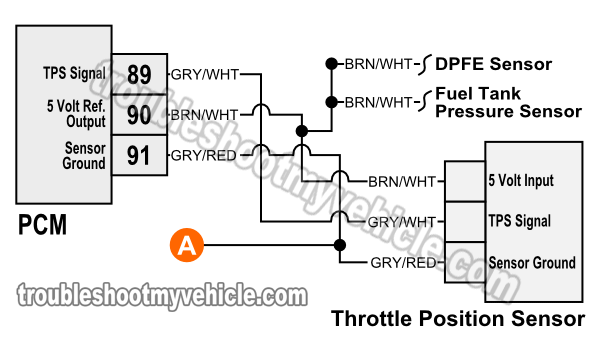
Alright, let's dive into the fascinating world of Ford Throttle Position Sensors, or TPS as we'll call them. Whether you're trying to diagnose a sputtering engine, planning an engine swap, or just want to deepen your automotive knowledge, understanding the TPS wiring diagram is crucial. We're going to break down everything, from the purpose of the diagram to troubleshooting tips, so you'll be equipped to tackle TPS-related issues with confidence.
Purpose of a Ford TPS Diagram
Think of the TPS diagram as the roadmap for your throttle position sensor's electrical system. It outlines the connections between the TPS, the Engine Control Unit (ECU), and other vital components. This diagram is absolutely essential for several reasons:
- Diagnostics: When your engine acts up, the TPS is a common suspect. The diagram helps you pinpoint wiring problems, short circuits, or open circuits that might be causing the sensor to malfunction.
- Repairs: Replacing a damaged TPS, repairing broken wires, or splicing in new connectors becomes a breeze when you have a clear understanding of the wiring layout.
- Modifications: Swapping engines, installing aftermarket ECUs, or adding performance parts often requires modifying the TPS wiring. The diagram is your guide to ensuring everything is hooked up correctly.
- Education: Even if you're not planning any immediate repairs, understanding the TPS diagram enhances your overall automotive knowledge and helps you understand how different systems interact.
In short, a TPS diagram is an indispensable tool for any serious DIY mechanic or car enthusiast.
Key Specs and Main Parts of a Ford TPS
Before we delve into the diagram itself, let's quickly review the key components and specifications of a typical Ford TPS.
- Throttle Position Sensor (TPS): This is the star of the show. It's usually mounted on the throttle body and measures the throttle plate's angle, sending this information to the ECU.
- ECU (Engine Control Unit): The brain of your engine, the ECU uses the TPS signal, along with other sensor data, to determine the correct air-fuel mixture and ignition timing.
- Throttle Body: The passage where air enters the engine. The throttle plate within controls the airflow.
- Wiring Harness: The network of wires that connect the TPS to the ECU and other components.
- Connector: The physical interface that plugs the TPS into the wiring harness.
Typical TPS units utilize a 3-wire configuration: 5V Reference, Ground, and Signal Wire. The ECU supplies a stable 5V to the TPS. As the throttle plate moves, the internal resistance within the TPS changes, altering the voltage on the signal wire. The ECU reads this voltage change and interprets it as the throttle position.
Understanding TPS Diagram Symbols
TPS diagrams aren't just a jumble of lines; they use specific symbols to represent different components and connections. Understanding these symbols is essential for interpreting the diagram correctly.
Lines:
- Solid Lines: Represent a direct wire connection.
- Dashed Lines: May represent shielded wires or indicate a connection that is optional or only present on certain models.
- Thick Lines: Might indicate a power wire carrying a significant amount of current.
Colors:
Wire colors are critical! Ford uses a color-coding system for its wiring, and the diagram will clearly indicate the color of each wire. Common colors include:
- Red: Usually indicates a power supply.
- Black: Typically represents ground.
- Green, Yellow, Blue: Often used for signal wires.
Always double-check the wire colors on the diagram against the actual wires in your vehicle.
Icons:
- Resistor Symbol (Zigzag Line): Indicates a resistor, which limits the flow of current. The TPS itself contains a potentiometer, which acts as a variable resistor.
- Ground Symbol (Downward-Pointing Triangle): Represents a connection to the vehicle's chassis ground.
- Connector Symbol (Interlocking Shapes): Shows where the wiring harness connects to the TPS.
- ECU Symbol: Usually a rectangle or box labeled "PCM" or "ECU" (Powertrain Control Module).
The diagram will also include alphanumeric labels to identify specific wires and components. For example, you might see "SIG" for the signal wire or "REF" for the 5V reference wire. Always cross-reference these labels with the actual wires on your TPS connector.
How a Ford TPS Works
The Ford TPS is essentially a variable resistor, also known as a potentiometer. Here's a simplified explanation of how it works:
- The ECU sends a constant 5-volt reference signal to the TPS.
- Inside the TPS, a wiper arm is connected to the throttle plate shaft. As the throttle plate rotates, the wiper arm moves along a resistive strip.
- The position of the wiper arm on the resistive strip determines the voltage that is sent back to the ECU on the signal wire.
- When the throttle is closed, the signal voltage is typically around 0.5 to 1.0 volts. As the throttle opens, the voltage increases proportionally, reaching around 4.5 volts at wide-open throttle (WOT).
- The ECU interprets this voltage change as the throttle position and adjusts the fuel injection and ignition timing accordingly.
A faulty TPS can send incorrect voltage signals to the ECU, leading to various engine problems, such as poor acceleration, stalling, rough idling, and even diagnostic trouble codes (DTCs).
Real-World Use: Basic Troubleshooting Tips
Now, let's put this knowledge to practical use. Here are a few basic troubleshooting tips when dealing with a Ford TPS:
- Check for DTCs: Use an OBD-II scanner to check for any trouble codes related to the TPS. Common codes include P0121, P0122, and P0123.
- Inspect the Wiring: Carefully examine the wiring harness and connector for any signs of damage, such as frayed wires, corrosion, or loose connections. Use the diagram to ensure all wires are properly connected.
- Measure Voltage: With the ignition on (engine off), use a multimeter to measure the voltage at the TPS connector. You should have approximately 5 volts on the reference wire and a variable voltage on the signal wire as you move the throttle plate.
- Check Resistance: Disconnect the TPS and use a multimeter to measure the resistance across the terminals. The resistance should change smoothly as you move the throttle plate. Erratic or sudden jumps in resistance indicate a faulty TPS.
- Visual Inspection: Check that the TPS is securely mounted on the throttle body. Verify that the throttle plate is moving freely and that the TPS is properly aligned.
If you suspect a faulty TPS, replacing it is often the simplest solution. However, always double-check the wiring and connections before replacing the sensor to rule out any other potential problems.
Safety Considerations
Working with automotive electrical systems can be dangerous if you're not careful. Here are a few safety precautions to keep in mind:
- Disconnect the Battery: Before working on any electrical components, disconnect the negative battery cable to prevent short circuits and electrical shocks.
- Be Mindful of the Fuel System: The fuel system operates under high pressure. Avoid working near fuel lines or injectors while the engine is running or immediately after it has been running.
- Use Proper Tools: Use insulated tools and a multimeter designed for automotive use.
- Work in a Well-Ventilated Area: Some automotive fluids and cleaners can be toxic. Work in a well-ventilated area to avoid inhaling harmful fumes.
- Don't Probe Wires Directly: Use back-probing techniques or specialized test leads to avoid damaging the insulation on the wires. Damaged insulation can lead to short circuits and other electrical problems.
The ECU itself is sensitive to static electricity. Avoid touching the pins on the ECU connector, and always ground yourself before handling the ECU.
We have a detailed Ford TPS wiring diagram file available for download to assist you further. This diagram will provide you with specific wiring information for various Ford models. With this diagram in hand and the knowledge you've gained from this article, you'll be well-equipped to diagnose and repair TPS-related issues with confidence.