Ford Turn Signal Switch Wiring Diagram
Alright, let's dive into the often-overlooked, but absolutely crucial, world of the Ford turn signal switch wiring diagram. This guide is designed to equip you, the experienced DIYer, with the knowledge needed to understand, troubleshoot, and even modify your Ford's turn signal system. Think of this as your cheat sheet to deciphering the electrical language that keeps your signals blinking correctly.
Purpose: Why You Need to Understand the Turn Signal Switch
Why bother digging into these diagrams? Well, a solid understanding of the turn signal switch wiring is essential for several reasons:
- Repair: A malfunctioning turn signal can range from a minor annoyance to a serious safety hazard. Instead of blindly replacing parts, diagnosing the issue using the wiring diagram pinpoints the fault, saving you time and money.
- Modification: Thinking about adding aftermarket lights, upgrading your hazard system, or integrating new features? The wiring diagram is your roadmap to a safe and successful project.
- Learning: Even if your signals are working fine, understanding the underlying system deepens your automotive knowledge and empowers you to tackle more complex electrical issues down the line. It's a fundamental building block for automotive electrical troubleshooting.
- Preventative Maintenance: Knowing where the critical components are located helps you check for corrosion, loose connections, or damaged wiring before they lead to complete failure.
Key Specs and Main Parts
Before we dive into the diagram itself, let's familiarize ourselves with the key components of a typical Ford turn signal system. This will help you understand what you're looking at on the schematic.
- Turn Signal Switch: This is the central control point, typically located on the steering column. It directs power to the appropriate turn signal lights (left or right) and also controls the hazard lights. It's a multi-position switch with complex internal wiring.
- Flasher Relay (or Electronic Flasher): This component provides the intermittent "blinking" action. It's essentially an oscillating switch that turns the lights on and off at a regular interval. Older systems used thermal flashers; newer vehicles often use electronic flashers.
- Turn Signal Bulbs: These are the lights themselves, typically located in the front and rear of the vehicle. They can be incandescent or LED, depending on the vehicle's age and trim.
- Hazard Switch: Usually a separate switch, the hazard switch activates all turn signal lights simultaneously. It often shares circuitry with the turn signal switch.
- Wiring Harness: This is the network of wires that connects all the components together. Wires are often color-coded to help identify them.
- Fuses: These are safety devices designed to protect the circuit from overloads. A blown fuse is often the first symptom of a problem.
- Grounds: All electrical circuits need a good ground connection to complete the circuit. Poor grounds are a common cause of electrical problems.
Symbols: Deciphering the Diagram Language
Understanding the symbols used in a wiring diagram is crucial for interpreting the information it provides. Here are some of the most common symbols you'll encounter:
- Solid Lines: Represent wires. The thickness of the line usually doesn't indicate anything special; it's just for clarity.
- Dashed Lines: Often indicate a ground connection or a shielded wire.
- Color Codes: Wires are almost always color-coded. The diagram will typically include a key that identifies each color and its corresponding function. For example, a wire labeled "GN/WH" might indicate a green wire with a white stripe.
- Circles or Dots: Represent connections between wires. A dot indicates a permanent connection; a lack of a dot indicates that the wires simply cross over each other without connecting.
- Rectangles: Often represent components such as relays, switches, or control modules.
- Zig-zag Lines: Represent resistors.
- Ground Symbol: Usually a series of horizontal lines decreasing in length, representing a connection to the vehicle's chassis ground.
- Lamp Symbol: Indicates a light bulb.
- Switch Symbols: Various symbols represent different types of switches (e.g., single-pole single-throw (SPST), single-pole double-throw (SPDT), etc.). The symbol shows the switch's normal (unactuated) state.
Pay close attention to the legend or key included with the diagram. It will provide specific definitions for the symbols used in that particular schematic.
How It Works: Tracing the Circuit
Here's a simplified explanation of how the turn signal circuit works. Imagine the process when you move the turn signal lever. The turn signal switch acts like a multi-way electrical router. When you activate the left turn signal, the switch connects the power source (usually from the battery, through a fuse) to the flasher relay, and then to the left turn signal bulbs (both front and rear). A similar process occurs for the right turn signal. The flasher relay interrupts the current flow at a regular interval, causing the lights to blink.
The hazard switch operates similarly, but it connects power to *all* turn signal bulbs simultaneously, bypassing the individual left/right selection of the turn signal switch (though often still going through the flasher relay portion of the circuit controlled by the turn signal switch assembly).
Real-World Use: Basic Troubleshooting Tips
Here are some common problems and how the wiring diagram can help you diagnose them:
- No Turn Signals: Check the fuse first! If the fuse is good, use a multimeter to check for power at the turn signal switch. If there's no power, trace the wiring back to the fuse box and battery. If there is power at the switch, the switch itself might be faulty.
- One Turn Signal Works, the Other Doesn't: Use the wiring diagram to trace the circuit for the non-working signal. Check the bulb first. Then, use a multimeter to check for power at the bulb socket. If there's no power, check the wiring between the switch and the bulb. Look for breaks, corrosion, or loose connections.
- Turn Signals Blink Too Fast: This usually indicates a burned-out bulb. When a bulb burns out, the circuit resistance changes, causing the flasher relay to blink faster. However, it can also be a sign of a faulty flasher relay (especially with LED bulbs).
- Turn Signals Stay On Constantly: This could be a short circuit in the wiring, a faulty turn signal switch, or a stuck flasher relay.
- Hazard Lights Don't Work: The hazard circuit is often separate from the turn signal circuit, though they often share the same flasher relay. Check the hazard fuse. If the fuse is good, check the hazard switch itself.
Using a Multimeter: A multimeter is your best friend for electrical troubleshooting. Learn how to use it to check for voltage, continuity, and resistance. Voltage checks confirm power presence. Continuity checks verify unbroken wire connections. Resistance checks can reveal shorts or open circuits. Consult your multimeter's user manual for instructions.
Safety: Handle with Care
Working with automotive electrical systems can be dangerous. Here are some important safety precautions:
- Disconnect the Battery: Always disconnect the negative battery cable before working on any electrical component. This prevents accidental short circuits and electrical shocks.
- Work in a Well-Ventilated Area: Batteries can produce explosive gases. Work in a well-ventilated area to prevent the buildup of these gases.
- Wear Safety Glasses: Protect your eyes from sparks and debris.
- Be Careful with Airbags: If you're working near the steering column, be extremely careful not to damage or accidentally trigger the airbag system. Accidental deployment can cause serious injury. Consult your vehicle's service manual for specific instructions on deactivating the airbag system before working on the steering column.
- Understand the Diagram: Don't start poking around wires without a clear understanding of the wiring diagram. You could cause more damage than you fix.
- Fuses are There for a Reason: Never bypass a fuse with a wire or other conductive material. Fuses protect the circuit from overloads and prevent fires.
Never underestimate the power of electricity! Proceed with caution and double-check your work.
Understanding the Ford turn signal switch wiring diagram empowers you to diagnose and repair common problems, modify your vehicle's electrical system, and deepen your automotive knowledge. Remember to always prioritize safety and consult your vehicle's service manual for specific instructions.
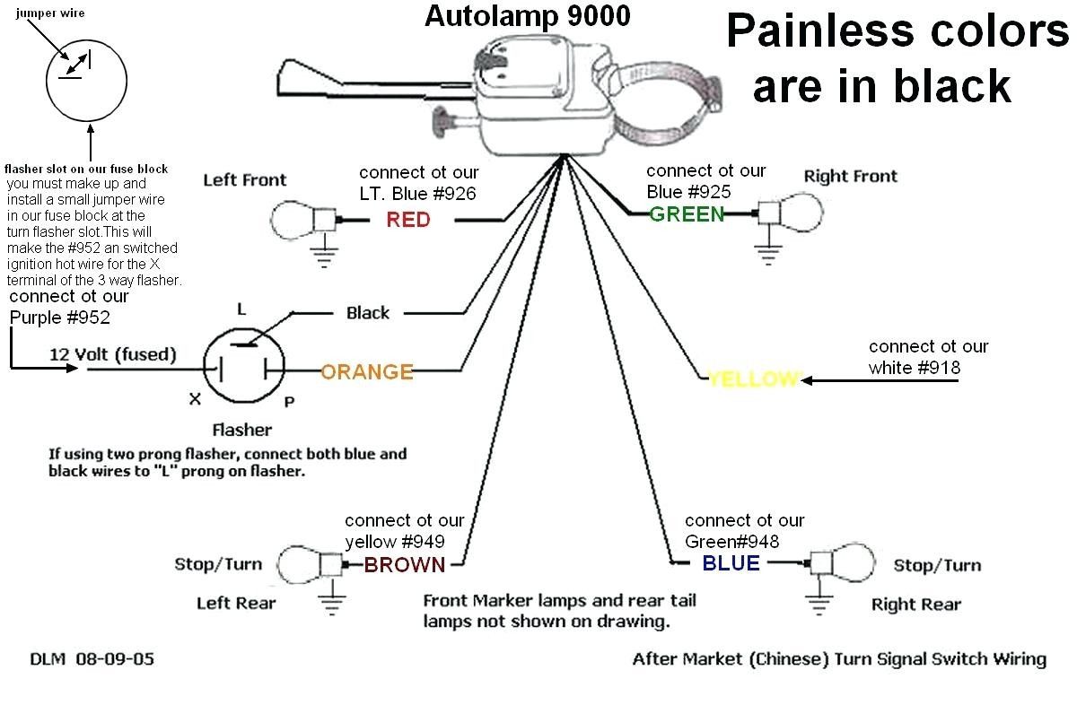
We have a high-resolution PDF file of a typical Ford turn signal switch wiring diagram that you can download. This diagram will provide a visual reference as you work through the troubleshooting steps. This comprehensive guide, paired with the diagram, should give you the confidence to tackle those electrical gremlins. Good luck!